


You also want an ePaper? Increase the reach of your titles
YUMPU automatically turns print PDFs into web optimized ePapers that Google loves.
COOLING SYSTEM 173<br />
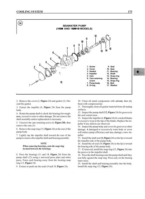
SEAWATER PUMP<br />
(1GM AND 1 GM1O MODELS)<br />
\ qi%.<br />
1. Screw 9. Seal<br />
2. Cover 10. Seal<br />
3. Gasket 11. Bearing<br />
4. Impeller 12. Shaft<br />
5. Cam 13. Snap ring<br />
6. Cam retaining 14. Bearing<br />
screw<br />
15. Snap ring<br />
16<br />
7. Pump body 16. Bolt<br />
1 8. O-ring 17. Washer<br />
2. Remove the cover (2, Figure 24) and gasket (3). Discard<br />
the gasket.<br />
3. Extract the impeller (4, Figure 24) from the pump<br />
body.<br />
4. Rotate the pump shaft to check the bearings for roughness,<br />
excessive wear or other damage. Do not remove the<br />
shaft assembly unless replacement is necessary.<br />
5. Unscrew the cam retaining screw (6, Figure 24), then<br />
remove the cam (5).<br />
6. Remove the snap ring (15, Figure 24) at the rear of the<br />
pump body.<br />
7. Lightly tap the impeller shaft toward the rear of the<br />
pump to remove the impeller shaft and bearing assembly.<br />
NOTE<br />
When removing bearings, note the snap ring<br />
located between the bearings.<br />
8. Press the bearings (1 1 and 14, Figure 24) from the<br />
pump shaft (12) using a universal press plate and arbor<br />
press. Force each bearing away from the locating snap<br />
ring (13, Figure 24).<br />
9. Extract or push out the seals (9 and 10, Figure 24).<br />
10. Clean all metal components with solvent, then dry<br />
them with compressed air.<br />
11. Thoroughly clean all gasket material from all mating<br />
surfaces.<br />
12. Inspect the pump shaft (12, Figure 24) for grooves in<br />
the seal contact area.<br />
13. Inspect the impeller (4, Figure 24) for cracked blades<br />
or excessive wear at the tips of the blades. Replace the impeller<br />
if any defects are observed.<br />
14. Inspect the pump body and cover for grooves or other<br />
damage. A damaged or excessively worn body or cover<br />
will reduce pump efficiency and may damage a new impeller.<br />
15. Install the shaft seal (9, Figure 24) so the lip is toward<br />
the impeller side of the pump body.<br />
16. Install the oil seal (10, Figure 24) so the lip is toward<br />
the bearing side of the pump body.<br />
17. If removed, install the snap ring (1 3, Figure 24) into<br />
the groove in the impeller shaft.<br />
18. Press the shaft bearings onto the pump shaft until they<br />
seat fully against the snap ring. Press only on the bearing<br />
inner races.<br />
19. Install the shaft and bearing assembly into the body.<br />
Install the snap ring (15, Figure 24).


