


Create successful ePaper yourself
Turn your PDF publications into a flip-book with our unique Google optimized e-Paper software.
ELECTRICAL SYSTEM 197<br />
3. To determine if a bulb is defective, substitute a good<br />
bulb. All warning lamps use the same type of bulb.<br />
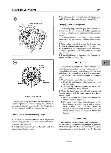
Coolant temperature<br />
\ sender<br />
Charging System Warning Lamp<br />
The warning lamp for the charging circuit should illuminate<br />
when the key switch is ON and the engine is not<br />
running, or when there is a malfunction in the charging<br />
circuit.<br />
1. To check the circuit for the charging system warning<br />
lamp, detach the lead from the L terminal on the alternator.<br />
2. With the key switch ON, ground the detached lead.<br />
The charge system warning lamp should come on.<br />
3. To determine if the charging system bulb is defective,<br />
substitute a good bulb. All warning lamps use the same<br />
type of bulb.<br />
4. If a good bulb does not light, check the charging system<br />
as described in Chapter Two.<br />
I<br />
WARNING LAMPS<br />
Positive<br />
iai<br />
. To<br />
891 nsors<br />
Engines covered by this manual are equipped with an<br />
instrument panel that has three warning lamps. The warning<br />
lamps illuminate to indicate high coolant temperature,<br />
low oil pressure or insufficient charging current.<br />
Coolant and Oil Pressure Warning Lamps<br />
1. To check the circuit for the coolant or oil pressure<br />
warning lamp, detach the lead from the coolant temperature<br />
or oil pressure sender.<br />
2. With the key switch ON, ground the sender lead. The<br />
warning lamp should come on.<br />
I<br />
ALARM BUZZER<br />
The alarm buzzer provides an audible warning in addition<br />
to the coolant and oil pressure warning lamps. Two<br />
types of alarm buzzers are used: a buzzer with two leads<br />
and a buzzer with multiple leads. Note the terminal locations<br />
in Figure 28 for the buzzer equipped with multiple<br />
leads.<br />
1. Check the alarm buzzer while it is installed.<br />
a. Detach the lead from the coolant temperature or oil<br />
pressure sender.<br />
b. With the key switch ON, ground the sender lead.<br />
The alarm buzzer should come on.<br />
2. Check the alarm buzzer with all leads disconnected<br />
from the buzzer or with the buzzer removed from the instrument<br />
panel.<br />
a. On the buzzer with multiple terminals, note the terminal<br />
locations in Figure 28.<br />
b. Connect a 12-volt battery to the terminals as follows:<br />
Connect a positive battery lead to positive<br />
buzzer terminal. Connect the negative battery lead<br />
to each of the remaining buzzer terminals. The<br />
buzzer should sound; if it does not, replace the<br />
buzzer.<br />
TACHOMETER<br />
Some engines may be equipped with a tachometer. A<br />
sensor located on the clutch housing (Figure 29) provides<br />
an electrical signal that drives the tachometer. The electromagnetic<br />
sensor counts the teeth on the flywheel ring


