


You also want an ePaper? Increase the reach of your titles
YUMPU automatically turns print PDFs into web optimized ePapers that Google loves.
TRANSMISSION-KBW SERIES 221<br />
2. Inspect the output shaft bearings and seal surfaces for<br />
excessive wear, grooving, metal transfer and discoloration<br />
from overheating.<br />
3. Inspect the key and output shaft keyway for damage.<br />
NOTE<br />
Shims behind the outer bearing race in the<br />
mounting flange determine bearing preload<br />
for the output shaft bearings. Save the shims<br />
and reinstall them ij- reusing the original<br />
parts.<br />
9. Refer to Steps 7 and 8 and disassemble the clutch components<br />
on the reverse gear.<br />
10. Lay the shift ring and pressure plate assembly flat.<br />
11. Remove the pressure plate return springs (24, Figure<br />
3), then lift off the top pressure plate (1 7) and remove the<br />
steel balls (18).<br />
12. Lift the shift ring (25, Figure 3) and driving plate (22)<br />
off the bottom pressure plate and remove the three remaining<br />
balls.<br />
13. Slip the shift ring (25, Figure 3) off the driving plate<br />
(22).<br />
14. Remove the alignment pins (2 1, Figure 3) and detent<br />
pins (20) with springs (19) from the driving plate (22).<br />
Inspection<br />
1. Check the gear teeth for excessive wear, corrosion or<br />
rust and mechanical damage. Check the teeth for galling,<br />
chips, cracks, missing pieces, distortion or discoloration<br />
from overheating. Check the splines for excessive wear or<br />
damage. Replace the gears if damaged.<br />
4. Inspect the input shaft bearing outer races in the transmission<br />
case and mounting flange. If either race is damaged<br />
or excessively worn, remove it using a suitable<br />
puller.<br />
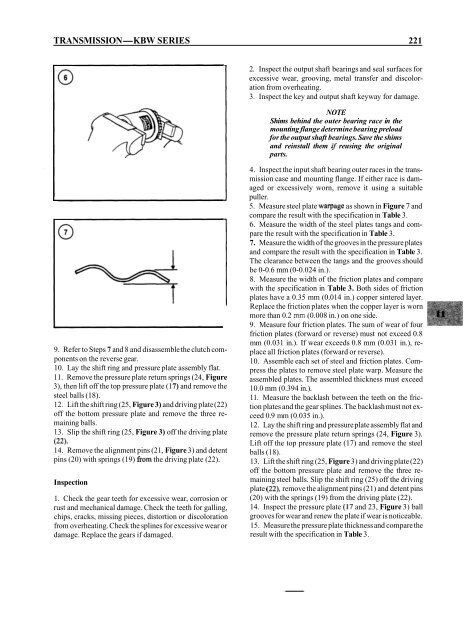
5. Measure steel plate warpage as shown in Figure 7 and<br />
compare the result with the specification in Table 3.<br />
6. Measure the width of the steel plates tangs and compare<br />
the result with the specification in Table 3.<br />
7. Measure the width of the grooves in the pressure plates<br />
and compare the result with the specification in Table 3.<br />
The clearance between the tangs and the grooves should<br />
be 0-0.6 mm (0-0.024 in.).<br />
8. Measure the width of the friction plates and compare<br />
with the specification in Table 3. Both sides of friction<br />
plates have a 0.35 mm (0.014 in.) copper sintered layer.<br />
Replace the friction plates when the copper layer is worn<br />
more than 0.2 mrn (0.008 in.) on one side.<br />
9. Measure four friction plates. The sum of wear of four<br />
friction plates (forward or reverse) must not exceed 0.8<br />
mm (0.03 1 in.). If wear exceeds 0.8 mm (0.03 1 in.), replace<br />
all friction plates (forward or reverse).<br />
10. Assemble each set of steel and friction plates. Compress<br />
the plates to remove steel plate warp. Measure the<br />
assembled plates. The assembled thickness must exceed<br />
10.0 mm (0.394 in.).<br />
11. Measure the backlash between the teeth on the friction<br />
plates and the gear splines. The backlash must not exceed<br />
0.9 mm (0.035 in.).<br />
12. Lay the shift ring and pressure plate assembly flat and<br />
remove the pressure plate return springs (24, Figure 3).<br />
Lift off the top pressure plate (17) and remove the steel<br />
balls (18).<br />
13. Lift the shift ring (25, Figure 3) and driving plate (22)<br />
off the bottom pressure plate and remove the three remaining<br />
steel balls. Slip the shift ring (25) off the driving<br />
plate (22), remove the alignment pins (2 1) and detent pins<br />
(20) with the springs (19) from the driving plate (22).<br />
14. Inspect the pressure plate (I7 and 23, Figure 3) ball<br />
grooves for wear and renew the plate if wear is noticeable.<br />
15. Measure the pressure plate thickness and compare the<br />
result with the specification in Table 3.


