


Create successful ePaper yourself
Turn your PDF publications into a flip-book with our unique Google optimized e-Paper software.
TRANSMISSION-KM SERIES 211<br />
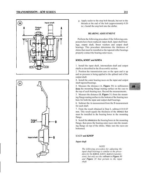
Output<br />
shaft<br />
Input shaft<br />
n<br />
g. Apply sealer to the stop bolt threads, but not to the<br />
threads at the end of the bolt (approximately 0.20<br />
in.). Install the stop bolt into the shifter.<br />
BEARING ADJUSTMENT<br />
Perform the following procedure if the following components<br />
have been replaced: input shaft, input shaft bearings,<br />
output shaft, thrust washers and output shaft<br />
bearings. This procedure determines the thickness of<br />
shims that must be installed so the tapered roller bearings<br />
properly contact the bearing outer races.<br />
KMZA, KM2C and KM3A<br />
1. Install the input shaft, intermediate shaft and output<br />
shafts as described in the Reassembly section.<br />
2. Position the transmission case so the open end is up<br />
and no pressure is being applied to the splined end of the<br />
output shaft.<br />
3. Install the outer bearing races on the input and output<br />
shaft tapered bearings.<br />
4. Measure the distance (A, Figure 30) in millimeters<br />
from the mounting flange mating surface on the case to<br />
the top of each bearing race. Record the measurements.<br />
5. Measure the distance (B, Figure 31) from the mounting<br />
flange mating surface to the bottom of the bearing race<br />
bore for both the input and output shaft bearings.<br />
6. Subtract the A measurement from the B measurement<br />
for each shaft.<br />
7. From the result obtained in Step 6, subtract 0.0-0.05<br />
mm. This result equals the thickness of the shim(s) that<br />
must be installed in the bearing bores in the mounting<br />
flange.<br />
8. Install the shim(s) in the bearing bores in the mounting<br />
flange, then press the bearing outer races into the mounting<br />
flange on top of the shims. Make sure the races are<br />
bottomed.<br />
KMZP and KM3P<br />
Input shaft<br />
NOTE<br />
The following procedure for adjusting the<br />
input shaft bearings is similar to the procedure<br />
for the KM2A, KM2C KM3A transmissions,<br />
but only use the callouts in Figure 30<br />
and Figure 31 that pertain to the input<br />
shaft.


