


You also want an ePaper? Increase the reach of your titles
YUMPU automatically turns print PDFs into web optimized ePapers that Google loves.
OPERATION, LUBRICATION, MAINTENANCE AND TUNE-UP 59<br />
@<br />
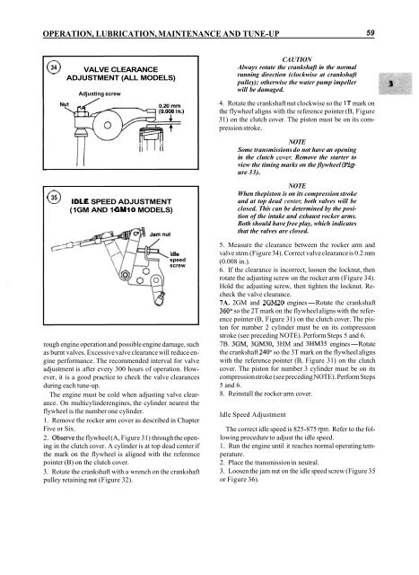
VALVE CLEARANCE<br />
ADJUSTMENT (ALL MODELS)<br />
Adjusting screw<br />
CA UTION<br />
Always rotate the crankshaft in the normal<br />
running direction (clockwise at crankshaft<br />
pulley); otherwise the water pump impeller<br />
will be damaged.<br />
4. Rotate the crankshaft nut clockwise so the 1T mark on<br />
the flywheel aligns with the reference pointer (B, Figure<br />
31) on the clutch cover. The piston must be on its compression<br />
stroke.<br />
NOTE<br />
Some transmissions do not have an opening<br />
in the clutch covel: Remove the starter to<br />
view the timing marks on the flywheel (Figure<br />
33).<br />
@ IDLE SPEED ADJUSTMENT<br />
(1 GM AND 1 GM1O MODELS)<br />
Idle<br />
speed<br />
screw<br />
rough engine operation and possible engine damage, such<br />
as burnt valves. Excessive valve clearance will reduce engine<br />
performance. The recommended interval for valve<br />
adjustment is after every 300 hours of operation. However,<br />
it is a good practice to check the valve clearances<br />
during each tune-up.<br />
The engine must be cold when adjusting valve clearance.<br />
On multicylinderengines, the cylinder nearest the<br />
flywheel is the number one cylinder.<br />
1. Remove the rocker arm cover as described in Chapter<br />
Five or Six.<br />
2. Observe the flywheel (A, Figure 31) through the opening<br />
in the clutch cover. A cylinder is at top dead center if<br />
the mark on the flywheel is aligned with the reference<br />
pointer (B) on the clutch cover.<br />
3. Rotate the crankshaft with a wrench on the crankshaft<br />
pulley retaining nut (Figure 32).<br />
NOTE<br />
When thepiston is on its compression stroke<br />
and at top dead centel; both valves will be<br />
closed. This can be determined by the position<br />
of the intake and exhaust rocker arms.<br />
Both should have free play, which indicates<br />
that the valves are closed.<br />
5. Measure the clearance between the rocker arm and<br />
valve stem (Figure 34). Correct valve clearance is 0.2 mm<br />
(0.008 in.).<br />
6. If the clearance is incorrect, loosen the locknut, then<br />
rotate the adjusting screw on the rocker arm (Figure 34).<br />
Hold the adjusting screw, then tighten the locknut. Recheck<br />
the valve clearance.<br />
7A. 2GM and 2GM20 engines-Rotate the crankshaft<br />
360" so the 2T mark on the flywheel aligns with the reference<br />
pointer (B, Figure 31) on the clutch cover. The piston<br />
for number 2 cylinder must be on its compression<br />
stroke (see preceding NOTE). Perform Steps 5 and 6.<br />
7B. 3GM, 3GM30, 3HM and 3HM35 engines-Rotate<br />
the crankshaft 240" so the 3T mark on the flywheel aligns<br />
with the reference pointer (B, Figure 31) on the clutch<br />
cover. The piston for number 3 cylinder must be on its<br />
compression stroke (see preceding NOTE). Perform Steps<br />
5 and 6.<br />
8. Reinstall the rocker arm cover.<br />
Idle Speed Adjustment<br />
The correct idle speed is 825-875 rpm. Refer to the following<br />
procedure to adjust the idle speed.<br />
1. Run the engine until it reaches normal operating temperature.<br />
2. Place the transmission in neutral.<br />
3. Loosen the jam nut on the idle speed screw (Figure 35<br />
or Figure 36).


