


Create successful ePaper yourself
Turn your PDF publications into a flip-book with our unique Google optimized e-Paper software.
204 CHAPTER TEN<br />
Intermediate shaft<br />
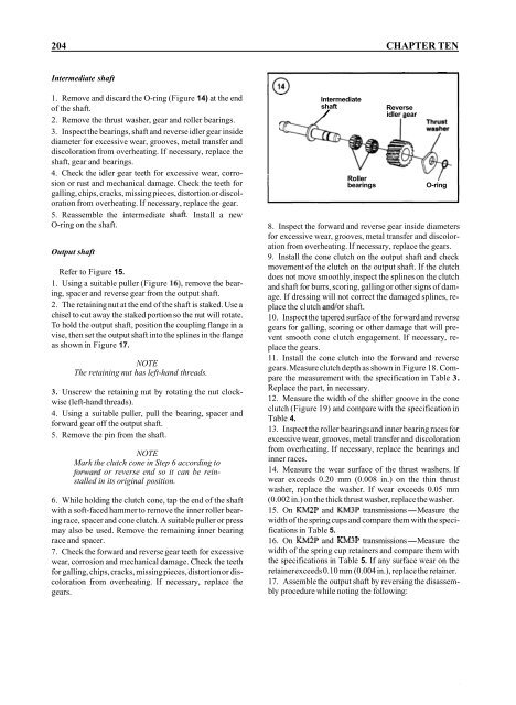
1. Remove and discard the O-ring (Figure 14) at the end<br />
of the shaft.<br />
2. Remove the thrust washer, gear and roller bearings.<br />
3. Inspect the bearings, shaft and reverse idler gear inside<br />
diameter for excessive wear, grooves, metal transfer and<br />
discoloration from overheating. If necessary, replace the<br />
shaft, gear and bearings.<br />
4. Check the idler gear teeth for excessive wear, corrosion<br />
or rust and mechanical damage. Check the teeth for<br />
galling, chips, cracks, missing pieces, distortion or discoloration<br />
from overheating. If necessary, replace the gear.<br />
5. Reassemble the intermediate shaft. Install a new<br />
O-ring on the shaft.<br />
Output shaft<br />
Refer to Figure 15.<br />
1. Using a suitable puller (Figure 16), remove the bearing,<br />
spacer and reverse gear from the output shaft.<br />
2. The retaining nut at the end of the shaft is staked. Use a<br />
chisel to cut away the staked portion so the nut will rotate.<br />
To hold the output shaft, position the coupling flange in a<br />
vise, then set the output shaft into the splines in the flange<br />
as shown in Figure 17.<br />
NOTE<br />
The retaining nut has left-hand threads.<br />
3. Unscrew the retaining nut by rotating the nut clockwise<br />
(left-hand threads).<br />
4. Using a suitable puller, pull the bearing, spacer and<br />
forward gear off the output shaft.<br />
5. Remove the pin from the shaft.<br />
NOTE<br />
Mark the clutch cone in Step 6 according to<br />
forward or reverse end so it can be reinstalled<br />
in its original position.<br />
6. While holding the clutch cone, tap the end of the shaft<br />
with a soft-faced hammer to remove the inner roller bearing<br />
race, spacer and cone clutch. A suitable puller or press<br />
may also be used. Remove the remaining inner bearing<br />
race and spacer.<br />
7. Check the forward and reverse gear teeth for excessive<br />
wear, corrosion and mechanical damage. Check the teeth<br />
for galling, chips, cracks, missing pieces, distortion or discoloration<br />
from overheating. If necessary, replace the<br />
gears.<br />
Intermediate<br />
shaft<br />
/<br />
Reverse<br />
idler aear<br />
Roller /<br />
bearings<br />
O-ring<br />
8. Inspect the forward and reverse gear inside diameters<br />
for excessive wear, grooves, metal transfer and discoloration<br />
from overheating. If necessary, replace the gears.<br />
9. Install the cone clutch on the output shaft and check<br />
movement of the clutch on the output shaft. If the clutch<br />
does not move smoothly, inspect the splines on the clutch<br />
and shaft for burrs, scoring, galling or other signs of damage.<br />
If dressing will not correct the damaged splines, replace<br />
the clutch and/or shaft.<br />
10. Inspect the tapered surface of the forward and reverse<br />
gears for galling, scoring or other damage that will prevent<br />
smooth cone clutch engagement. If necessary, replace<br />
the gears.<br />
11. Install the cone clutch into the forward and reverse<br />
gears. Measure clutch depth as shown in Figure 18. Compare<br />
the measurement with the specification in Table 3.<br />
Replace the part, in necessary.<br />
12. Measure the width of the shifter groove in the cone<br />
clutch (Figure 19) and compare with the specification in<br />
Table 4.<br />
13. Inspect the roller bearings and inner bearing races for<br />
excessive wear, grooves, metal transfer and discoloration<br />
from overheating. If necessary, replace the bearings and<br />
inner races.<br />
14. Measure the wear surface of the thrust washers. If<br />
wear exceeds 0.20 mm (0.008 in.) on the thin thrust<br />
washer, replace the washer. If wear exceeds 0.05 mm<br />
(0.002 in.) on the thick thrust washer, replace the washer.<br />
15. On KM2P and KM3P transmissions-Measure the<br />
width of the spring cups and compare them with the specifications<br />
in Table 5.<br />
16. On KM2P and KM3P transmissions-Measure the<br />
width of the spring cup retainers and compare them with<br />
the specifications in Table 5. If any surface wear on the<br />
retainer exceeds 0.10 mm (0.004 in.), replace the retainer.<br />
17. Assemble the output shaft by reversing the disassembly<br />
procedure while noting the following:


