


You also want an ePaper? Increase the reach of your titles
YUMPU automatically turns print PDFs into web optimized ePapers that Google loves.
222 CHAPTER ELEVEN<br />
16. Measure the return spring end gap (Figure 8) and<br />
compare the result with the specification in Table 3.<br />
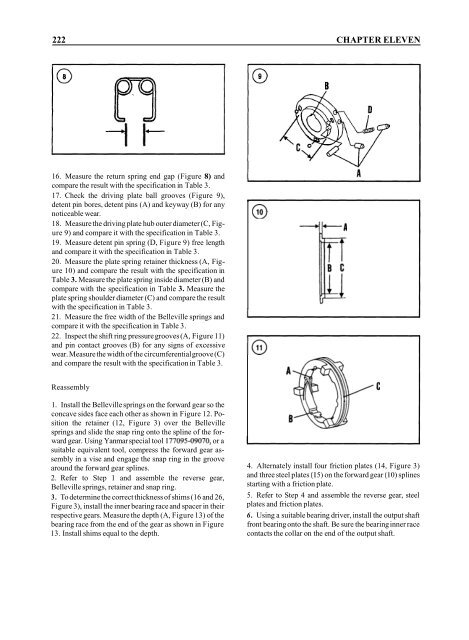
17. Check the driving plate ball grooves (Figure 9),<br />
detent pin bores, detent pins (A) and keyway (B) for any<br />
noticeable wear.<br />
18. Measure the driving plate hub outer diameter (C, Figure<br />
9) and compare it with the specification in Table 3.<br />
19. Measure detent pin spring (D, Figure 9) free length<br />
and compare it with the specification in Table 3.<br />
20. Measure the plate spring retainer thickness (A, Figure<br />
10) and compare the result with the specification in<br />
Table 3. Measure the plate spring inside diameter (B) and<br />
compare with the specification in Table 3. Measure the<br />
plate spring shoulder diameter (C) and compare the result<br />
with the specification in Table 3.<br />
2 1. Measure the free width of the Belleville springs and<br />
compare it with the specification in Table 3.<br />
22. Inspect the shift ring pressure grooves (A, Figure 11)<br />
and pin contact grooves (B) for any signs of excessive<br />
wear. Measure the width of the circumferential groove (C)<br />
and compare the result with the specification in Table 3.<br />
Reassembly<br />
1. Install the Belleville springs on the forward gear so the<br />
concave sides face each other as shown in Figure 12. Position<br />
the retainer (12, Figure 3) over the Belleville<br />
springs and slide the snap ring onto the spline of the forward<br />
gear. Using Yanmar special tool 177095-09070, or a<br />
suitable equivalent tool, compress the forward gear assembly<br />
in a vise and engage the snap ring in the groove<br />
around the forward gear splines.<br />
2. Refer to Step 1 and assemble the reverse gear,<br />
Belleville springs, retainer and snap ring.<br />
3. To determine the correct thickness of shims (16 and 26,<br />
Figure 3), install the inner bearing race and spacer in their<br />
respective gears. Measure the depth (A, Figure 13) of the<br />
bearing race from the end of the gear as shown in Figure<br />
13. Install shims equal to the depth.<br />
4. Alternately install four friction plates (14, Figure 3)<br />
and three steel plates (I 5) on the forward gear (I 0) splines<br />
starting with a friction plate.<br />
5. Refer to Step 4 and assemble the reverse gear, steel<br />
plates and friction plates.<br />
6. Using a suitable bearing driver, install the output shaft<br />
front bearing onto the shaft. Be sure the bearing inner race<br />
contacts the collar on the end of the output shaft.


