


Create successful ePaper yourself
Turn your PDF publications into a flip-book with our unique Google optimized e-Paper software.
TRANSMISSION-KM SERIES 201<br />
0<br />
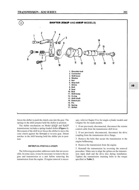
SHIFTER (KMPP AND KM3P MODELS)<br />
8<br />
1. Shoulder bolt<br />
2. Connector<br />
3. Shift lever<br />
4. Washer<br />
5. Nut<br />
6. Stop bolt<br />
7. Shims<br />
8. Bolt<br />
9. Seal<br />
10. Bolt<br />
11. Shift body<br />
12. O-ring<br />
13. Shift shaft<br />
14. Detent pin<br />
15. Pin<br />
16. Spring<br />
17. Shifter<br />
forces the shifter to push the clutch cone into the gear. The<br />
springs in the shift actuator hold the shifter in position.<br />
The shifter mechanism on Model KM2P and KM3P<br />
transmissions includes a spring-loaded shifter (Figure 4).<br />
Movement of the shift lever forces the shifter to move the<br />
cone clutch against the forward or reverse gear. Detent<br />
notches in the shift housing hold the shifter pin in position.<br />
REMOVALIINSTALLATION<br />
The following procedure addresses units that are accessible.<br />
In some cases, it may be necessary to remove the engine<br />
and transmission as a unit before removing the<br />
transmission from the engine. If engine removal is neces-<br />
sary, refer to Chapter Five for single-cylinder models and<br />
Chapter Six for multi-models.<br />
1. If not previously disconnected, disconnect the remote<br />
control cable from the transmission shift lever.<br />
2. If not previously disconnected, disconnect the drive<br />
coupling from the transmission drive flange.<br />
3. Remove the bolts that secure the transmission to the<br />
engine bellhousing.<br />
4. Remove the transmission from the engine.<br />
5. Reinstall the transmission by reversing the removal<br />
procedure. Make sure to align the splines on the transmission<br />
input shaft and the drive disc during installation.<br />
Tighten the transmission retaining bolts to the torque<br />
specified in Table 2.


