


Create successful ePaper yourself
Turn your PDF publications into a flip-book with our unique Google optimized e-Paper software.
70 CHAPTER FIVE<br />
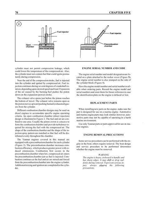
Fuel injector<br />
Open -<br />
chamber<br />
chamber<br />
cylinder must not permit compression leakage, which<br />
could lower the temperature of the compressed air. Also,<br />
the cylinder must not contain fuel that could ignite prematurely<br />
during compression.<br />
Near the end of the compression stroke, fuel is injected<br />
into the cylinder and ignited by compressed air. Fuel injection<br />
continues during several degrees of crankshaft rotation,<br />
depending upon desired speed and load. Expansion<br />
of the air caused by the burning fuel pushes the piston<br />
down on the expansion (power) stroke.<br />
The exhaust valve opens just before the piston reaches<br />
the bottom of travel. The exhaust valve remains open as<br />
the piston moves upward pushing burned (exhausted) gasses<br />
from the cylinder.<br />
Different combustion chamber designs may be used on<br />
diesel engines to accomodate specific engine operating<br />
criteria. An open combustion chamber (direct injection)<br />
design is illustrated in Figure 2. The fuel and air are confined<br />
to one area. Usually the piston crown is concave to<br />
form the combustion chamber and provide turbulence required<br />
for mixing the fuel with the compressed air. The<br />
shape of the combustion chamber and the shape of the injection<br />
spray pattern are matched so that fuel will be distributed<br />
evenly throughout the chamber.<br />
The Yanmar engines covered in this manual are<br />
equipped with a precombustion chamber for each cylinder<br />
(Figure 2). The precombustion chamber increases combustion<br />
efficiency, which produces greater power with reduced<br />
emmissions. Combustion first occurs in the<br />
precombustion chamber when hot, compressed air enters<br />
the precombustion chamber just as fuel is injected. Combustion<br />
continues as the fuel and air are mixed and forced<br />
from the precombustion chamber into the engine cylinder.<br />
Additional mixing and ignition are completed in the cylinder.<br />
ENGINE SERIAL NUMBER AND CODE<br />
The engine serial number and model designation are located<br />
on a plate attached to the rocker cover (Figure 3).<br />
The engine serial number is also stamped on the side of<br />
the cylinder block (Figure 4).<br />
Have the engine model number and serial number available<br />
when ordering parts. Record the engine model and<br />
serial numbers and store them for future reference in case<br />
the identification plate on the engine is defaced or lost.<br />
REPLACEMENT PARTS<br />
When installing new parts on the engine, make sure the<br />
part is designed for use on a marine engine. Automotive<br />
and marine engine parts may look similar; however, automotive<br />
parts may not be capable of operating in a harsh<br />
marine environment.<br />
Use only Yanmar parts or parts approved for use on marine<br />
engines.<br />
ENGINE REMOVAL PRECAUTIONS<br />
Some service procedures can be performed with the engine<br />
in the boat; others require removal. The boat design<br />
and service procedure to be performed determines<br />
whether the engine must be removed.<br />
WARNING<br />
The engine is heavy, awkward to handle and<br />
has sharp edges. It may shift or drop suddenly<br />
during removal. Toprevent serious injury,<br />
always observe the following<br />
precautions.


