


You also want an ePaper? Increase the reach of your titles
YUMPU automatically turns print PDFs into web optimized ePapers that Google loves.
FUEL INJECTION AND GOVERNOR SYSTEMS 157<br />
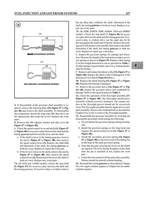
MAIN GOVERNOR SPRING<br />
SECONDARY GOVERNOR SPRING<br />
4. If disassembly of the governor shaft assembly is required,<br />
remove the retaining bolts (29, Figure 47 or Figure<br />
48) and remove the shaft assembly. To disassemble<br />
the components, detach the snap ring (16), then drive out<br />
the tapered pins that retain the levers. Replace the worn<br />
parts.<br />
5. Remove the idle adjuster bracket and side cover (4,<br />
Figure 47 or Figure 48).<br />
6. Check the speed control lever and shaft (12, Figure 47<br />
or Figure 48) for excessive play between the shaft and the<br />
timing gearcase and between the lever and the shaft.<br />
a. If the shaft is loose in the timing gearcase, remove<br />
the nut (1, Figure 47 or Figure 48), then remove<br />
the speed control lever (3). Remove the shaft (12)<br />
and determine if the shaft, the timing gearcase or<br />
both are worn. Replace or repair the worn part.<br />
b. If the lever is loose on the shaft, remove the nut (1,<br />
Figure 47 or Figure 48), then remove the speed<br />
control lever (3). Determine if the lever, the shaft or<br />
both are worn. Replace any worn parts.<br />
7A. On 1 GM and 1 GMIO models--Check the stop shaft<br />
(5, Figure 47) for excessive play between the shaft and<br />
the timing gearcase. If excessive play is evident, remove<br />
the nut (42), then withdraw the shaft. Determine if the<br />
shaft, the timing gearcase or both are worn. Replace or repair<br />
any worn parts.<br />
7B. On ZGM, 2GM20, 3GM, 3GM30, 3HM and 3HM35<br />
models--Check the stop shaft (5, Figure 48) for excessive<br />
play between the shaft and the timing gearcase. If excessive<br />
play is evident, drive out the taper pin (6) by<br />
driving against the small end of the pin. Remove the locking<br />
screw (7). Remove the nut (42), then remove the shaft.<br />
Determine if the shaft, the timing gearcase or both are<br />
worn. Replace or repair any worn parts.<br />
8. Inspect the governor springs for damage and distortion.<br />
Measure the length of the main and secondary governor<br />
springs as shown in Figure 49. Replace either spring<br />
if its free length dimension is not as specified in Table 2.<br />
If either spring is questionable, take it to a Yanmar dealership<br />
for testing.<br />
9. Remove and inspect the thrust collar (32, Figure 47 or<br />
Figure 48). Replace the thrust collar if damaged or if the<br />
thickness is less than 2.9 rnrn (0.114 in.).<br />
10. Remove the thrust bearing (33, Figure 47 or Figure<br />
48). Replace the bearing if damaged.<br />
11. Remove the governor sleeve (34, Figure 47 or Figure<br />
48). Inspect the governor sleeve and crankshaft for<br />
damage. Refer to the specifications in Table 3.<br />
12. Check the operation of the flyweight assembly (37,<br />
Figure 47 or Figure 48). The flyweights should move<br />
smoothly without excessive looseness. The contact surface<br />
in the flyweight groove should not be excessively<br />
worn. The flyweight assembly must be replaced as a complete<br />
assembly. Remove the crankshaft nut as described in<br />
Chapter Five or Six to remove the flyweight assembly.<br />
13. Reassemble the governor assembly by reversing the<br />
disassembly procedure while noting the following:<br />
a. Do not distort the governor springs during installation.<br />
b. Install the governor springs so the long hook end<br />
engages the speed control lever (12, Figure 47 or<br />
Figure 48).<br />
c. Install the secondary governor spring (14, Figure<br />
47 or Figure 48) so the lower end of the spring fits<br />
in the loop on the main governor spring.<br />
d. Note that the pins securing the levers on the shafts<br />
are tapered. The lever should fit tightly on the shaft<br />
after the pin is installed. If not, replace the worn<br />
part.<br />
e. Check the movement of all the parts after assembly.<br />
Motion should be smooth without binding.<br />
14. Reinstall the timing gearcase as described in Chapter<br />
Five for single cylinder engines or Chapter Six for multicylinder<br />
engines.


