Lightweight Concrete for High Strength - Expanded Shale & Clay
Lightweight Concrete for High Strength - Expanded Shale & Clay
Lightweight Concrete for High Strength - Expanded Shale & Clay

You also want an ePaper? Increase the reach of your titles
YUMPU automatically turns print PDFs into web optimized ePapers that Google loves.
CSS at Level of Bottom Strands (µε)<br />
4500<br />
4000<br />
3500<br />
3000<br />
2500<br />
2000<br />
1500<br />
1000<br />
500<br />
0<br />
0 10 20 30 40<br />
Crack<br />
Lt<br />
V=169 K<br />
V=242 K<br />
V=291 K<br />
V=315 K<br />
V=339K<br />
V=355 K<br />
Distance From Girder End (Inches)<br />
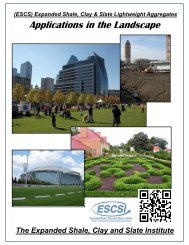
Shear Crack Data<br />
Distance From End (Inches) 5.0 7.0 12.5 20.5 23.5 26.5 34.0 42.0 44.0 47.5<br />
Applied Shear at Cracking (Kips) 169 315 242 339 315 355 339 339 291 355<br />
Figure C.27 G1A-East CSS and Shear Cracking vs. Distance from Girder End<br />
Shear cracking across the bottom strands within the transfer length region initiated large<br />
increases in strand end slip. Russell (1992) reported this phenomenon. Despite several shear<br />
cracks in the transfer length region, tests G1B-West and G2B-West showed no slip because of<br />
the double stirrup density. Tests G1A-East and G2A-East showed slip, but at very small or<br />
almost acceptable levels. Russell reported that additional bond stresses can be developed<br />
beyond initial strand slip and that small slips are not always followed by complete anchorage<br />
failure. Russell also reported that closely spaced cracks were an indication of good bond and<br />
wide crack spacing indicated poor bond. Both of Russell’s observations were confirmed in the<br />
present tests.<br />
<strong>Concrete</strong> grade also played a significant role in determining development length. Table<br />
5.11 clearly demonstrates a reduction in development length based on concrete grade alone. The<br />
G1 series girders had compressive strengths on average approximately 1500 psi less than the G2<br />
series girders. The water cement ratios were approximately 0.29 <strong>for</strong> the G1 series girders and<br />
0.23 <strong>for</strong> the G2 series girders. A significant difference between the two mix designs was the<br />
amount of silica fume. The G1 series girders had 2 percent silica fume by weight of the total<br />
C-18