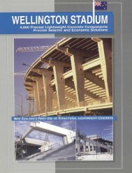
Lightweight Concrete for High Strength - Expanded Shale & Clay
Lightweight Concrete for High Strength - Expanded Shale & Clay
Lightweight Concrete for High Strength - Expanded Shale & Clay

You also want an ePaper? Increase the reach of your titles
YUMPU automatically turns print PDFs into web optimized ePapers that Google loves.
Table 5.5 –Transfer Length Results (inches)<br />
G1A G1B G1C G2A G2B G2C<br />
East West East West East West East West East West East West<br />
19.5 18.75 25.00 18.75 28.00 21.50 17.50 13.25 13.00 13.00 19.00 18.00<br />
FREE FREE FREE<br />
5.7 Girder Tests and Results<br />
Each girder was loaded monotonically until failure at a load of approximately 400 kips.<br />
Loading proceeded in increments of approximately 30 kips or in deflection increments of about<br />
0.25 inches. After each load or deflection increment, concrete surface strain (CSS) readings,<br />
deflection readings, crack spacings, and VWSG readings were recorded. Readings were also<br />
taken at special occurrences such as first flexural or shear crack observation or initial strand slip.<br />
Table 5.6 provides an overview of experimental results listing failure types, ultimate strain<br />
values and moments at cracking and ultimate conditions. The failure types were classified using<br />
the definitions below:<br />
FL - The girder failed by “BOTH” crushing of the deck and yielding of the strands.<br />
SH - The girder failed purely in shear. It did not meet the criteria <strong>for</strong> a flexural failure.<br />
SH/FL - The girder failed predominantly in shear, but still yielded the strands and crushed the<br />
deck. The two failure states occurred almost simultaneously.<br />
SH-SL - The girder underwent a shear failure initiated by the strands slipping.<br />
FL/SH-SL or SH-SL/FL - The girder underwent both failure modes with one occurring more<br />
predominantly than the other. Both failures would result in yielding of the strands and crushing<br />
of the deck.<br />
Although there are five failure types listed in Table 5.6, the failures fell into two major<br />
categories; flexural failures and shear failures.<br />
5.7.1 Flexural Failures<br />
Figure 5.12 shows a photo of girder test G1-B West, a typical flexural failure. The<br />
vertical lines indicate the location of shear rein<strong>for</strong>cement. Flexural failures were ductile in<br />
nature. A typical flexural failure showed flexural cracks extending from the bottom of the girder<br />
up into the deck and evenly spaced shear cracks less than 0.02 inches in width between the<br />
5-15