

Design and Realization of a Prototype Hardware Platform for ...
Design and Realization of a Prototype Hardware Platform for ...
Design and Realization of a Prototype Hardware Platform for ...

Create successful ePaper yourself
Turn your PDF publications into a flip-book with our unique Google optimized e-Paper software.
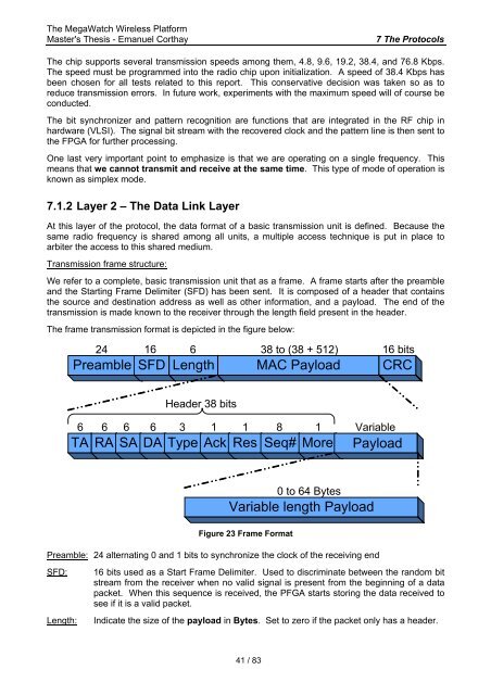
The MegaWatch Wireless <strong>Plat<strong>for</strong>m</strong>Master's Thesis - Emanuel Corthay7 The ProtocolsThe chip supports several transmission speeds among them, 4.8, 9.6, 19.2, 38.4, <strong>and</strong> 76.8 Kbps.The speed must be programmed into the radio chip upon initialization. A speed <strong>of</strong> 38.4 Kbps hasbeen chosen <strong>for</strong> all tests related to this report. This conservative decision was taken so as toreduce transmission errors. In future work, experiments with the maximum speed will <strong>of</strong> course beconducted.The bit synchronizer <strong>and</strong> pattern recognition are functions that are integrated in the RF chip inhardware (VLSI). The signal bit stream with the recovered clock <strong>and</strong> the pattern line is then sent tothe FPGA <strong>for</strong> further processing.One last very important point to emphasize is that we are operating on a single frequency. Thismeans that we cannot transmit <strong>and</strong> receive at the same time. This type <strong>of</strong> mode <strong>of</strong> operation isknown as simplex mode.7.1.2 Layer 2 – The Data Link LayerAt this layer <strong>of</strong> the protocol, the data <strong>for</strong>mat <strong>of</strong> a basic transmission unit is defined. Because thesame radio frequency is shared among all units, a multiple access technique is put in place toarbiter the access to this shared medium.Transmission frame structure:We refer to a complete, basic transmission unit that as a frame. A frame starts after the preamble<strong>and</strong> the Starting Frame Delimiter (SFD) has been sent. It is composed <strong>of</strong> a header that containsthe source <strong>and</strong> destination address as well as other in<strong>for</strong>mation, <strong>and</strong> a payload. The end <strong>of</strong> thetransmission is made known to the receiver through the length field present in the header.The frame transmission <strong>for</strong>mat is depicted in the figure below:24 16 6 38 to (38 + 512) 16 bitsPreamble SFD Length MAC Payload CRCHeader 38 bits6 6 6 6 3 1 1 8 1 VariableTA RA SA DA Type Ack Res Seq# More Payload0 to 64 BytesVariable length PayloadFigure 23 Frame FormatPreamble: 24 alternating 0 <strong>and</strong> 1 bits to synchronize the clock <strong>of</strong> the receiving endSFD:Length:16 bits used as a Start Frame Delimiter. Used to discriminate between the r<strong>and</strong>om bitstream from the receiver when no valid signal is present from the beginning <strong>of</strong> a datapacket. When this sequence is received, the PFGA starts storing the data received tosee if it is a valid packet.Indicate the size <strong>of</strong> the payload in Bytes. Set to zero if the packet only has a header.41 / 83


