

Design and Realization of a Prototype Hardware Platform for ...
Design and Realization of a Prototype Hardware Platform for ...
Design and Realization of a Prototype Hardware Platform for ...

Create successful ePaper yourself
Turn your PDF publications into a flip-book with our unique Google optimized e-Paper software.
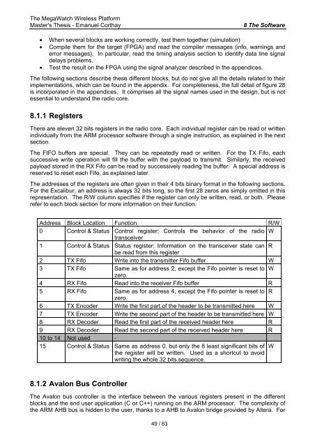
The MegaWatch Wireless <strong>Plat<strong>for</strong>m</strong>Master's Thesis - Emanuel Corthay8 The S<strong>of</strong>tware• When several blocks are working correctly, test them together (simulation)• Compile them <strong>for</strong> the target (FPGA) <strong>and</strong> read the compiler messages (info, warnings <strong>and</strong>error messages). In particular, read the timing analysis section to identify data line signaldelays problems.• Test the result on the FPGA using the signal analyzer described in the appendices.The following sections describe these different blocks, but do not give all the details related to theirimplementations, which can be found in the appendix. For completeness, the full detail <strong>of</strong> figure 28is incorporated in the appendices. It comprises all the signal names used in the design, but is notessential to underst<strong>and</strong> the radio core.8.1.1 RegistersThere are eleven 32 bits registers in the radio core. Each individual register can be read or writtenindividually from the ARM processor s<strong>of</strong>tware through a single instruction, as explained in the nextsection.The FIFO buffers are special. They can be repeatedly read or written. For the TX Fifo, eachsuccessive write operation will fill the buffer with the payload to transmit. Similarly, the receivedpayload stored in the RX Fifo can be read by successively reading the buffer. A special address isreserved to reset each Fifo, as explained later.The addresses <strong>of</strong> the registers are <strong>of</strong>ten given in their 4 bits binary <strong>for</strong>mat in the following sections.For the Excalibur, an address is always 32 bits long, so the first 28 zeros are simply omitted in thisrepresentation. The R/W column specifies if the register can only be written, read, or both. Pleaserefer to each block section <strong>for</strong> more in<strong>for</strong>mation on their function.Address Block Location Function R/W0 Control & Status Control register; Controls the behavior <strong>of</strong> the radio Wtransceiver1 Control & Status Status register; In<strong>for</strong>mation on the transceiver state can Rbe read from this register2 TX Fifo Write into the transmitter Fifo buffer W3 TX Fifo Same as <strong>for</strong> address 2, except the Fifo pointer is reset to Wzero.4 RX Fifo Read into the receiver Fifo buffer R5 RX Fifo Same as <strong>for</strong> address 4, except the Fifo pointer is reset to Rzero.6 TX Encoder Write the first part <strong>of</strong> the header to be transmitted here W7 TX Encoder Write the second part <strong>of</strong> the header to be transmitted here W8 RX Decoder Read the first part <strong>of</strong> the received header here R9 RX Decoder Read the second part <strong>of</strong> the received header here R10 to 14 Not used -15 Control & Status Same as address 0, but only the 8 least significant bits <strong>of</strong> Wthe register will be written. Used as a shortcut to avoidwriting the whole 32 bits sequence.8.1.2 Avalon Bus ControllerThe Avalon bus controller is the interface between the various registers present in the differentblocks <strong>and</strong> the end user application (C or C++) running on the ARM processor. The complexity <strong>of</strong>the ARM AHB bus is hidden to the user, thanks to a AHB to Avalon bridge provided by Altera. For49 / 83


