

Design and Realization of a Prototype Hardware Platform for ...
Design and Realization of a Prototype Hardware Platform for ...
Design and Realization of a Prototype Hardware Platform for ...

You also want an ePaper? Increase the reach of your titles
YUMPU automatically turns print PDFs into web optimized ePapers that Google loves.
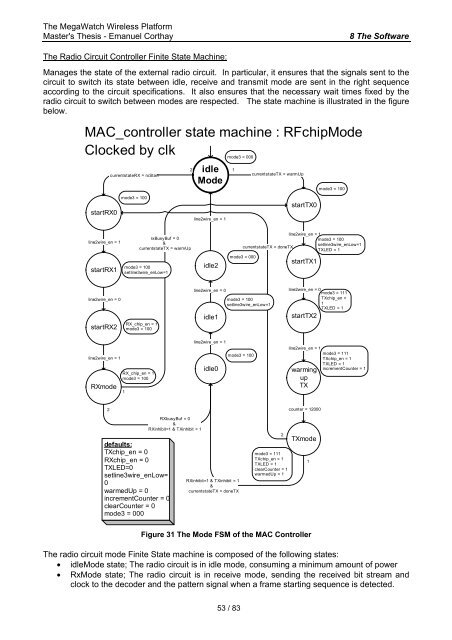
The MegaWatch Wireless <strong>Plat<strong>for</strong>m</strong>Master's Thesis - Emanuel Corthay8 The S<strong>of</strong>twareThe Radio Circuit Controller Finite State Machine:Manages the state <strong>of</strong> the external radio circuit. In particular, it ensures that the signals sent to thecircuit to switch its state between idle, receive <strong>and</strong> transmit mode are sent in the right sequenceaccording to the circuit specifications. It also ensures that the necessary wait times fixed by theradio circuit to switch between modes are respected. The state machine is illustrated in the figurebelow.MAC_controller state machine : RFchipModeClocked by clkcurrentstateRX = rxStartidleMode2 1mode3 = 000currentstateTX = warmUpmode3 = 100startRX0mode3 = 100line2wire_en = 1startTX0line2wire_en = 1startRX1rxBusyBuf = 0¤tstateTX = warmUpmode3 = 100setline3wire_enLow=1idle2line2wire_en = 1mode3 = 100setline3wire_enLow=1currentstateTX = doneTXTXLED = 1mode3 = 000startTX1line2wire_en = 0startRX2RX_chip_en = 1mode3 = 100line2wire_en = 0idle1mode3 = 100setline3wire_enLow=1line2wire_en = 0mode3 = 111TXchip_en =1TXLED = 1startTX2line2wire_en = 1RXmodeRX_chip_en = 1mode3 = 1001line2wire_en = 1idle0mode3 = 100line2wire_en = 1warmingupTXmode3 = 111TXchip_en = 1TXLED = 1incrementCounter = 12counter = 12000defaults:TXchip_en = 0RXchip_en = 0TXLED=0setline3wire_enLow=0warmedUp = 0incrementCounter = 0clearCounter = 0mode3 = 000RXbusyBuf = 0&RXinhibit=1 & TXinhibit = 1RXinhibit=1 & TXinhibit = 1¤tstateTX = doneTX2mode3 = 111TXchip_en = 1TXLED = 1clearCounter = 1warmedUp = 1TXmode1Figure 31 The Mode FSM <strong>of</strong> the MAC ControllerThe radio circuit mode Finite State machine is composed <strong>of</strong> the following states:• idleMode state; The radio circuit is in idle mode, consuming a minimum amount <strong>of</strong> power• RxMode state; The radio circuit is in receive mode, sending the received bit stream <strong>and</strong>clock to the decoder <strong>and</strong> the pattern signal when a frame starting sequence is detected.53 / 83


