Tecnai on-line help manual -- Alignments - UT Southwestern
Tecnai on-line help manual -- Alignments - UT Southwestern
Tecnai on-line help manual -- Alignments - UT Southwestern
- No tags were found...
You also want an ePaper? Increase the reach of your titles
YUMPU automatically turns print PDFs into web optimized ePapers that Google loves.
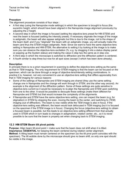
<str<strong>on</strong>g>Tecnai</str<strong>on</strong>g> <strong>on</strong>-<strong>line</strong> <strong>help</strong> <strong>Alignments</strong> 57<str<strong>on</strong>g>Tecnai</str<strong>on</strong>g> 12 Software versi<strong>on</strong> 2ProcedureThe alignment procedure c<strong>on</strong>sists of four steps :• A first step (using the Nanoprobe mode settings) in which the specimen is brought to focus (theeucentric height, which should have been aligned in the Nanoprobe image alignment previously) byadjusting the Z height.• A sec<strong>on</strong>d step in which the image is focused (setting the objective-lens preset for HM-STEM) andnext the beam is focused (setting the intensity preset). If necessary stigmate the image (if the imageis astigmatic, the beam will also appear astigmatic but this is due to the image, not to the shape ofthe beam itself, and if you "stigmate" the beam with an astigmatic image, you will actually make thebeam (and thus the STEM image) astigmatic. Note: Since we want to have the same objective-lenssetting in Nanoprobe and HM-STEM, the alternative to setting it by looking at the image is to makesure you can observe the objective-lens excitati<strong>on</strong> (%; e.g. by dragging it into a status display panelor popping up the System status) and making the value in step two the same as in step <strong>on</strong>e.• A third step in which the microscope is switched to diffracti<strong>on</strong> and the diffracti<strong>on</strong> pattern is centered.• A fourth similar to step three but now for all spot sizes (except 3 which has been d<strong>on</strong>e already).Descripti<strong>on</strong>In principle there is no a priori requirement in scanning to define the objective-lens setting as the sameas that in TEM imaging. The <strong>on</strong>ly requirement for STEM imaging is that the beam can be focused <strong>on</strong> thespecimen, which can be d<strong>on</strong>e through a range of objective-lens/intensity setting combinati<strong>on</strong>s. Inpractice it is, however, not very c<strong>on</strong>venient to use an objective-lens setting that differs appreciably fromthat in TEM imaging for various reas<strong>on</strong>s:• Some of the settings of Nanoprobe and STEM imaging are shared (they use the same setting;change <strong>on</strong>e in Nanoprobe and the change will work through in STEM, and the other way around). Anexample is the alignment of the diffracti<strong>on</strong> pattern. Some of these settings are quite sensitive toobjective-lens current so it would be necessary to re-align the Nanoprobe and STEM up<strong>on</strong> switchingfrom <strong>on</strong>e to the other. It would be possible to decouple these settings (make them different forNanoprobe and STEM) but that would increase the complexity of the alignments.• If Nanoprobe and STEM have the same objective-lens setting, <strong>on</strong>e can inspect the beam (e.g. forstigmati<strong>on</strong>) in STEM by stopping the scan, moving the beam to the center, and switching to (TEM)imaging (out of diffracti<strong>on</strong>). The beam is now visible while the TEM image is also in focus. If theobjective-lens setting was different, the beam would look defocused in TEM imaging (but it is focused<strong>on</strong> the specimen if the STEM image is in focus). Changing the focus (objective-lens setting) to obtaina focused beam is possible, but this leads to an objective-lens setting different from that actuallyused in STEM which in turn leads to changes in astigmatism, rotati<strong>on</strong> center, etc., so it is neverpossible to be sure that the beam is properly set when changing back to STEM imaging.12.3 HM-STEM Beam tilt pivot pointsPurpose: Align beam tilt pivot point = make sure that the beam does not shift when it is tilted.Importance: ESSENTIAL for keeping the beam centered during rotati<strong>on</strong> center alignment.Method: A tilting beam must remain centered <strong>on</strong> the specimen (so the tilt pivot point coincides with thespecimen). The tilt wobble d<strong>on</strong>e by the microscope should give no beam shift, so <strong>on</strong>ly <strong>on</strong>e spot shouldbe visible in the image.


