observed flow at <strong>the</strong> Willamette River at Wilsonvillestream-gaging station (14198000, discontinued),where only 1 year of record was available <strong>for</strong> comparisonpurposes. PRMS was used to simulate 350 mi 2 ofintervening drainage area (4 percent of <strong>the</strong> basin).Statistical results <strong>for</strong> <strong>the</strong> calibration period indicate anabsolute error of 3.3 percent <strong>and</strong> a small bias of about-1.5 percent (table 12).AN EXAMPLE WATER-QUALITYAPPLICATIONThe ultimate goal of precipitation-runoff simulation<strong>and</strong> channel-flow routing is to model water qualityin a basin context. There was no intent during thisphase of <strong>the</strong> project to calibrate a water-quality model<strong>for</strong> a particular set of constituents; however, a linkagefrom <strong>the</strong> constructed hydrologic models to a waterqualitymodel was developed. The following sectiondescribes an application of <strong>the</strong> model used <strong>for</strong> waterqualitysimulation. Flow data were supplied toDAFLOW by both measured inflows <strong>and</strong> by using <strong>the</strong>rainfall-runoff simulation of <strong>the</strong> Pudding River, a subbasinof <strong>the</strong> Willamette River. The output of <strong>the</strong>DAFLOW model was used to drive <strong>the</strong> BLTM modelby Jobson <strong>and</strong> Schoellhamer (1987) to simulate <strong>the</strong>injection <strong>and</strong> subsequent dispersion of dye. At thispoint, <strong>the</strong> model is ready to simulate o<strong>the</strong>r conservativeconstituents. Decay rates are required <strong>for</strong> <strong>the</strong> simulationof nonconservative constituents, such asnutrients or dissolved oxygen, whose fate <strong>and</strong> transportare linked to <strong>the</strong>ir consumption by biota <strong>and</strong> bychemical interactions. Field studies made to measure<strong>the</strong>se decay rates are a prerequisite to nutrient or dissolvedoxygen modeling.Description of <strong>the</strong> Example BasinThe Pudding River is a highly sinuous streamincised in silt. The river drains primarily agriculturall<strong>and</strong>s on <strong>the</strong> eastern, lower-elevation side of <strong>the</strong> MolallaRiver Basin (fig. 21). Basin characteristics are illustratedin figure 6. There is considerable State <strong>and</strong>Federal interest in major nonpoint sources of contaminationfrom urban <strong>and</strong> agricultural areas in <strong>the</strong> WillametteRiver Basin, <strong>and</strong> <strong>the</strong> Pudding River Basinprovides a good example of water-quality problemsfrom <strong>the</strong>se sources. The Pudding River has been targeted<strong>for</strong> intensive study by both ODEQ <strong>and</strong> <strong>the</strong>USGS. Point sources of contamination are also importantin <strong>the</strong> basin, <strong>and</strong> although <strong>the</strong>se sources have beenidentified, <strong>the</strong>ir effect on stream water quality is notwell known.During summer <strong>and</strong> fall periods, dissolved oxygenconcentration in <strong>the</strong> Pudding River frequently isbelow 90 percent of saturation <strong>and</strong> at times is below70 percent of saturation (Oregon Department of EnvironmentalQuality, 1994). Excessive growth of algaecontributes to dissolved oxygen problems in <strong>the</strong> mainstem. In <strong>the</strong> summer, high concentrations of nutrients,warm temperatures, favorable light conditions, <strong>and</strong>low flows promote algal growth. In <strong>the</strong> late fall, winter,<strong>and</strong> spring, when high flow occurs, excessivelyhigh counts of bacteria <strong>and</strong> sediment concentrationsoccur frequently.Sources of nutrients, sediment, bacteria, <strong>and</strong>oxygen-consuming substances in <strong>the</strong> Pudding RiverBasin are not well identified. Some of <strong>the</strong>se contaminantscome from identified point sources, includingwastewater-treatment plants <strong>and</strong> food-processingindustries. Nonpoint sources, however, also are knownto be important. The major sources of sediment <strong>and</strong>bacteria in <strong>the</strong> Pudding River are probably nonpointsources; <strong>the</strong> contaminants are <strong>the</strong> result of activitiesthat disturb <strong>the</strong> l<strong>and</strong> surface, which include farming,logging, <strong>and</strong> urbanization. Inputs of nutrients probablyderive from similar sources; however, during <strong>the</strong> summermonths, when nutrient inputs promote algalgrowth, shallow <strong>and</strong> deep ground water may also be aproportionally major nutrient source to <strong>the</strong> main-stemPudding River <strong>and</strong> its tributaries. Water-quality transportmodeling of this basin can provide valuableinsight to <strong>the</strong> complex processes that occur <strong>and</strong> providea tool <strong>for</strong> management.Use of <strong>the</strong> Branched-Lagrangian TransportModelA one-dimensional water-quality model basedon <strong>the</strong> Lagrangian reference frame was developed <strong>for</strong>use in simulating <strong>the</strong> transport of conservative <strong>and</strong>nonconservative constituents <strong>and</strong> <strong>for</strong> applying reactionsbetween constituents <strong>for</strong> branched river systems,tidal canal systems, <strong>and</strong> deltaic channels (Jobson <strong>and</strong>Schoellhamer, 1987). BLTM solves <strong>the</strong> convectivedispersionequation by using a Lagrangian referenceframe in which <strong>the</strong> computational nodes move with<strong>the</strong> flow. Unsteady flow hydraulics must be supplied to<strong>the</strong> model, <strong>and</strong> constituent concentrations are assumedto have no effect on <strong>the</strong> hydraulics. A flow model suchas DAFLOW can be used to supply <strong>the</strong> hydraulic58
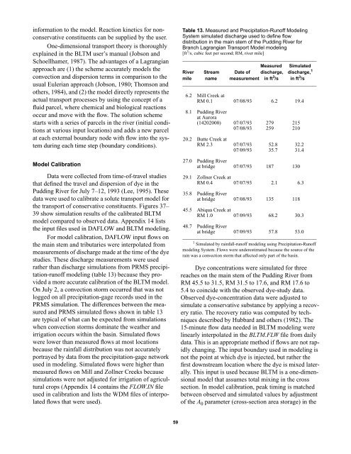
in<strong>for</strong>mation to <strong>the</strong> model. Reaction kinetics <strong>for</strong> nonconservativeconstituents can be supplied by <strong>the</strong> user.One-dimensional transport <strong>the</strong>ory is thoroughlyexplained in <strong>the</strong> BLTM user’s manual (Jobson <strong>and</strong>Schoellhamer, 1987). The advantages of a Lagrangianapproach are (1) <strong>the</strong> scheme accurately models <strong>the</strong>convection <strong>and</strong> dispersion terms in comparison to <strong>the</strong>usual Eulerian approach (Jobson, 1980; Thomson <strong>and</strong>o<strong>the</strong>rs, 1984), <strong>and</strong> (2) <strong>the</strong> model directly represents <strong>the</strong>actual transport processes by using <strong>the</strong> concept of afluid parcel, where chemical <strong>and</strong> biological reactionsoccur <strong>and</strong> move with <strong>the</strong> flow. The solution schemestarts with a series of parcels in <strong>the</strong> river (initial conditionsat various input locations) <strong>and</strong> adds a new parcelat each external boundary node with flow into <strong>the</strong> systemduring each time step (boundary conditions).Model CalibrationData were collected from time-of-travel studiesthat defined <strong>the</strong> travel <strong>and</strong> dispersion of dye in <strong>the</strong>Pudding River <strong>for</strong> July 7–12, 1993 (Lee, 1995). Thesedata were used to calibrate a solute transport model <strong>for</strong><strong>the</strong> transport of conservative constituents. Figures 37–39 show simulation results of <strong>the</strong> calibrated BLTMmodel compared to observed data. Appendix 14 lists<strong>the</strong> input files used in DAFLOW <strong>and</strong> BLTM modeling.For model calibration, DAFLOW input flows on<strong>the</strong> main stem <strong>and</strong> tributaries were interpolated frommeasurements of discharge made at <strong>the</strong> time of <strong>the</strong> dyestudies. These discharge measurements were usedra<strong>the</strong>r than discharge simulations from PRMS precipitation-runoffmodeling (table 13) because <strong>the</strong>y provideda more accurate calibration of <strong>the</strong> BLTM model.On July 2, a convection storm occurred that was notlogged on all precipitation-gage records used in <strong>the</strong>PRMS simulation. The differences between <strong>the</strong> measured<strong>and</strong> PRMS simulated flows shown in table 13are typical of what can be expected from simulationswhen convection storms dominate <strong>the</strong> wea<strong>the</strong>r <strong>and</strong>irrigation occurs within <strong>the</strong> basin. Simulated flowswere lower than measured flows at most locationsbecause <strong>the</strong> rainfall distribution was not accuratelyportrayed by data from <strong>the</strong> precipitation-gage networkused in modeling. Simulated flows were higher thanmeasured flows on Mill <strong>and</strong> Zollner Creeks becausesimulations were not adjusted <strong>for</strong> irrigation of agriculturalcrops (Appendix 14 contains <strong>the</strong> FLOW.IN fileused in calibration <strong>and</strong> lists <strong>the</strong> WDM files of interpolatedflows that were used).Table 13. Measured <strong>and</strong> <strong>Precipitation</strong>-<strong>Runoff</strong> ModelingSystem simulated discharge used to define flowdistribution in <strong>the</strong> main stem of <strong>the</strong> Pudding River <strong>for</strong>Branch Lagrangian Transport Model modeling[ft 3 /s, cubic feet per second; RM, river mile]____________________________________________________Measured SimulatedRiver Stream Date of discharge, discharge, 1mile name measurement in ft 3 /s in ft 3 /s____________________________________________________6.2 Mill Creek atRM 0.1 07/08/93 6.2 19.48.1 Pudding Riverat Aurora(14202000) 07/07/93 279 21507/08/93 259 21020.2 Butte Creek atRM 2.3 07/07/93 52.8 32.207/09/93 35.7 31.427.0 Pudding Riverat bridge 07/07/93 187 13029.1 Zollner Creek atRM 0.4 07/07/93 2.1 6.335.8 Pudding Riverat bridge 07/08/93 135 11845.5 Abiqua Creek atRM 1.0 07/09/93 68.2 30.348.7 Pudding Riverat bridge 07/09/93 57.8 53.0____________________________________________________1 Simulated by rainfall-runoff modeling using <strong>Precipitation</strong>-<strong>Runoff</strong>modeling System. Flows were underestimated because <strong>the</strong> source of <strong>the</strong>rain was a convection storm that affected only part of <strong>the</strong> basin.Dye concentrations were simulated <strong>for</strong> threereaches on <strong>the</strong> main stem of <strong>the</strong> Pudding River fromRM 45.5 to 31.5, RM 31.5 to 17.6, <strong>and</strong> RM 17.6 to5.4 to coincide with <strong>the</strong> observed dye-study data.Observed dye-concentration data were adjusted tosimulate a conservative substance by applying a recoveryratio. The recovery ratio was computed by techniquesdescribed by Hubbard <strong>and</strong> o<strong>the</strong>rs (1982). The15-minute flow data needed in BLTM modeling werelinearly interpolated in <strong>the</strong> BLTM.FLW file from dailydata. This is an appropriate method if flows are not rapidlychanging. The input boundary used in modeling isnot <strong>the</strong> point at which dye is injected, but ra<strong>the</strong>r <strong>the</strong>first downstream location where <strong>the</strong> dye is mixed laterally.This input is used because BLTM is a one-dimensionalmodel that assumes total mixing in <strong>the</strong> crosssection. In model calibration, peak timing is matchedbetween observed <strong>and</strong> simulated values by adjustmentof <strong>the</strong> A 0 parameter (cross-section area storage) in <strong>the</strong>59
- Page 1:
Precipitation-Runoff and Streamflow
- Page 4 and 5:
U.S. DEPARTMENT OF THE INTERIORBRUC
- Page 6 and 7:
Determining Travel Time and Dilutio
- Page 8 and 9:
2. Stream-gaging stations used to c
- Page 10 and 11:
Page Intentionally Blank
- Page 12 and 13:
network-routing models where availa
- Page 14 and 15:
made on the main stem at base-flow
- Page 16 and 17:
Figure 1. Willamette River Basin, O
- Page 18 and 19: EvapotranspirationINPUTSAirtemperat
- Page 20 and 21: Table 1. Climate stations used to c
- Page 22 and 23: Table 2. Stream-gaging stations use
- Page 24 and 25: Figure 4. Mean annual precipitation
- Page 26 and 27: Major Land Use MapHydrologic Soil G
- Page 28 and 29: 0.5 mi 2 , created in the merge of
- Page 30 and 31: Table 6. Geology and soils matrix o
- Page 32 and 33: tion value of the HRU class by the
- Page 34 and 35: Table 8. Selected monthly basinwide
- Page 36 and 37: Figure 9. Location of Precipitation
- Page 38 and 39: Table 11. Statistical analyses of P
- Page 40 and 41: flow can become a significant compo
- Page 42 and 43: diffusion at selected grid interval
- Page 44 and 45: samples were collected at various d
- Page 46 and 47: 3,0002,500June 21-30, 1993September
- Page 48 and 49: stream network is shown on figure 1
- Page 50 and 51: 122˚30´ 15´122˚00´121˚45´Roc
- Page 52 and 53: 123˚22´30´´ 123˚15´ 123˚00´
- Page 54 and 55: 123˚00´´ 45´30´122˚15´45˚15
- Page 56 and 57: YamhillRiver123˚45´ 30´ 15´123
- Page 58 and 59: 123˚07´30´´ 123˚00´ 45´ 30´
- Page 60 and 61: 123˚07´30´´ 123˚00´ 45´ 30´
- Page 62 and 63: 44˚15´14166000122˚07´30´´Will
- Page 64 and 65: 122˚15´ 122˚00´121˚52´30´´4
- Page 66 and 67: 44˚52´30´´45´122˚15´ 122˚00
- Page 70 and 71: DAFLOW model, and peak amplitude is
- Page 72 and 73: 20DYE CONCENTRATION, IN MICROGRAMS
- Page 74 and 75: ARC-INFO and Geographic Information
- Page 76 and 77: WILL.WDMData-base file(Observed pre
- Page 78 and 79: WILL.WDMData-base fileSWSTATSFreque
- Page 80 and 81: Jobson, H.E., 1980, Comment on A ne
- Page 82 and 83: Page Intentionally Blank
- Page 84 and 85: APPENDIX 1. STREAM GEOMETRY FOR MAI
- Page 86 and 87: APPENDIX 1. STREAM GEOMETRY FOR MAI
- Page 88 and 89: APPENDIX 1. STREAM GEOMETRY FOR MAI
- Page 90 and 91: APPENDIX 1. STREAM GEOMETRY FOR MAI
- Page 92 and 93: APPENDIX 1. STREAM GEOMETRY FOR MAI
- Page 94 and 95: APPENDIX 1. STREAM GEOMETRY FOR MAI
- Page 96 and 97: APPENDIX 1. STREAM GEOMETRY FOR MAI
- Page 98 and 99: APPENDIX 1. STREAM GEOMETRY FOR MAI
- Page 100 and 101: APPENDIX 1. STREAM GEOMETRY FOR MAI
- Page 102 and 103: APPENDIX 1. STREAM GEOMETRY FOR MAI
- Page 104 and 105: APPENDIX 1. STREAM GEOMETRY FOR MAI
- Page 106 and 107: APPENDIX 1. STREAM GEOMETRY FOR MAI
- Page 108 and 109: APPENDIX 1. STREAM GEOMETRY FOR MAI
- Page 110 and 111: APPENDIX 2. ARC MACRO LANGUAGE (AML
- Page 112 and 113: APPENDIX 2. ARC MACRO LANGUAGE (AML
- Page 114 and 115: APPENDIX 2. ARC MACRO LANGUAGE (AML
- Page 116 and 117: APPENDIX 2. ARC MACRO LANGUAGE (AML
- Page 118 and 119:
APPENDIX 2. ARC MACRO LANGUAGE (AML
- Page 120 and 121:
APPENDIX 2. ARC MACRO LANGUAGE (AML
- Page 122 and 123:
APPENDIX 3. DEFINITIONS OF PARAMETE
- Page 124 and 125:
APPENDIX 3. DEFINITIONS OF PARAMETE
- Page 126 and 127:
APPENDIX 4. MEASUREMENTS USED TO DE
- Page 128 and 129:
APPENDIX 4. MEASUREMENTS USED TO DE
- Page 130 and 131:
APPENDIX 4. MEASUREMENTS USED TO DE
- Page 132 and 133:
APPENDIX 4. MEASUREMENTS USED TO DE
- Page 134 and 135:
APPENDIX 5. EXAMPLE PRECIPITATION-R
- Page 136 and 137:
APPENDIX 5. EXAMPLE PRECIPITATION-R
- Page 138 and 139:
APPENDIX 6. DIFFUSION ANALOGY FLOW
- Page 140 and 141:
APPENDIX 6. DIFFUSION ANALOGY FLOW
- Page 142 and 143:
APPENDIX 6. DIFFUSION ANALOGY FLOW
- Page 144 and 145:
APPENDIX 6. DIFFUSION ANALOGY FLOW
- Page 146 and 147:
APPENDIX 6. DIFFUSION ANALOGY FLOW
- Page 148 and 149:
APPENDIX 6. DIFFUSION ANALOGY FLOW
- Page 150 and 151:
APPENDIX 7. PROGRAMMING STEPS TO IN
- Page 152 and 153:
APPENDIX 8. PROGRAMMING STEPS TO DE
- Page 154 and 155:
APPENDIX 8. PROGRAMMING STEPS TO DE
- Page 156 and 157:
APPENDIX 8. PROGRAMMING STEPS TO DE
- Page 158 and 159:
APPENDIX 8. PROGRAMMING STEPS TO DE
- Page 160 and 161:
150Climatemaxtempmintempprecipitati
- Page 162 and 163:
APPENDIX 10. DIRECTORY TREE AND DES
- Page 164 and 165:
APPENDIX 10. DIRECTORY TREE AND DES
- Page 166 and 167:
APPENDIX 10. DIRECTORY TREE AND DES
- Page 168 and 169:
APPENDIX 10. DIRECTORY TREE AND DES
- Page 170 and 171:
APPENDIX 10. DIRECTORY TREE AND DES
- Page 172 and 173:
APPENDIX 10. DIRECTORY TREE AND DES
- Page 174 and 175:
APPENDIX 10. DIRECTORY TREE AND DES
- Page 176 and 177:
APPENDIX 10. DIRECTORY TREE AND DES
- Page 178 and 179:
APPENDIX 10. DIRECTORY TREE AND DES
- Page 180 and 181:
APPENDIX 11. DIRECTORY TREES AND DE
- Page 182 and 183:
APPENDIX 11. DIRECTORY TREES AND DE
- Page 184 and 185:
APPENDIX 12. DIRECTORY FOR will.wdm
- Page 186 and 187:
APPENDIX 12. DIRECTORY FOR will.wdm
- Page 188 and 189:
APPENDIX 12. DIRECTORY FOR will.wdm
- Page 190 and 191:
APPENDIX 12. DIRECTORY FOR will.wdm
- Page 192 and 193:
APPENDIX 12. DIRECTORY FOR will.wdm
- Page 194 and 195:
APPENDIX 12. DIRECTORY FOR will.wdm
- Page 196 and 197:
APPENDIX 13. PROGRAMMING STEPS FOR
- Page 198 and 199:
APPENDIX 13. PROGRAMMING STEPS FOR
- Page 200 and 201:
APPENDIX 13. PROGRAMMING STEPS FOR
- Page 202 and 203:
APPENDIX 14. INPUT FILES FOR BRANCH
- Page 204 and 205:
APPENDIX 14. INPUT FILES FOR BRANCH
- Page 206 and 207:
APPENDIX 14. INPUT FILES FOR BRANCH