Precipitation-Runoff and Streamflow-Routing Models for the ...
Precipitation-Runoff and Streamflow-Routing Models for the ...
Precipitation-Runoff and Streamflow-Routing Models for the ...
- No tags were found...

You also want an ePaper? Increase the reach of your titles
YUMPU automatically turns print PDFs into web optimized ePapers that Google loves.
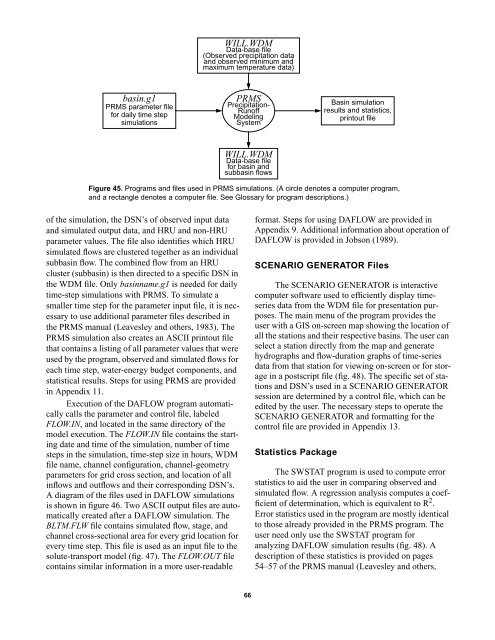
WILL.WDMData-base file(Observed precipitation data<strong>and</strong> observed minimum <strong>and</strong>maximum temperature data)basin.g1PRMS parameter file<strong>for</strong> daily time stepsimulationsPRMS<strong>Precipitation</strong>-<strong>Runoff</strong>ModelingSystemBasin simulationresults <strong>and</strong> statistics,printout fileWILL.WDMData-base file<strong>for</strong> basin <strong>and</strong>subbasin flowsFigure 45. Programs <strong>and</strong> files used in PRMS simulations. (A circle denotes a computer program,<strong>and</strong> a rectangle denotes a computer file. See Glossary <strong>for</strong> program descriptions.)of <strong>the</strong> simulation, <strong>the</strong> DSN’s of observed input data<strong>and</strong> simulated output data, <strong>and</strong> HRU <strong>and</strong> non-HRUparameter values. The file also identifies which HRUsimulated flows are clustered toge<strong>the</strong>r as an individualsubbasin flow. The combined flow from an HRUcluster (subbasin) is <strong>the</strong>n directed to a specific DSN in<strong>the</strong> WDM file. Only basinname.g1 is needed <strong>for</strong> dailytime-step simulations with PRMS. To simulate asmaller time step <strong>for</strong> <strong>the</strong> parameter input file, it is necessaryto use additional parameter files described in<strong>the</strong> PRMS manual (Leavesley <strong>and</strong> o<strong>the</strong>rs, 1983). ThePRMS simulation also creates an ASCII printout filethat contains a listing of all parameter values that wereused by <strong>the</strong> program, observed <strong>and</strong> simulated flows <strong>for</strong>each time step, water-energy budget components, <strong>and</strong>statistical results. Steps <strong>for</strong> using PRMS are providedin Appendix 11.Execution of <strong>the</strong> DAFLOW program automaticallycalls <strong>the</strong> parameter <strong>and</strong> control file, labeledFLOW.IN, <strong>and</strong> located in <strong>the</strong> same directory of <strong>the</strong>model execution. The FLOW.IN file contains <strong>the</strong> startingdate <strong>and</strong> time of <strong>the</strong> simulation, number of timesteps in <strong>the</strong> simulation, time-step size in hours, WDMfile name, channel configuration, channel-geometryparameters <strong>for</strong> grid cross section, <strong>and</strong> location of allinflows <strong>and</strong> outflows <strong>and</strong> <strong>the</strong>ir corresponding DSN’s.A diagram of <strong>the</strong> files used in DAFLOW simulationsis shown in figure 46. Two ASCII output files are automaticallycreated after a DAFLOW simulation. TheBLTM.FLW file contains simulated flow, stage, <strong>and</strong>channel cross-sectional area <strong>for</strong> every grid location <strong>for</strong>every time step. This file is used as an input file to <strong>the</strong>solute-transport model (fig. 47). The FLOW.OUT filecontains similar in<strong>for</strong>mation in a more user-readable<strong>for</strong>mat. Steps <strong>for</strong> using DAFLOW are provided inAppendix 9. Additional in<strong>for</strong>mation about operation ofDAFLOW is provided in Jobson (1989).SCENARIO GENERATOR FilesThe SCENARIO GENERATOR is interactivecomputer software used to efficiently display timeseriesdata from <strong>the</strong> WDM file <strong>for</strong> presentation purposes.The main menu of <strong>the</strong> program provides <strong>the</strong>user with a GIS on-screen map showing <strong>the</strong> location ofall <strong>the</strong> stations <strong>and</strong> <strong>the</strong>ir respective basins. The user canselect a station directly from <strong>the</strong> map <strong>and</strong> generatehydrographs <strong>and</strong> flow-duration graphs of time-seriesdata from that station <strong>for</strong> viewing on-screen or <strong>for</strong> storagein a postscript file (fig. 48). The specific set of stations<strong>and</strong> DSN’s used in a SCENARIO GENERATORsession are determined by a control file, which can beedited by <strong>the</strong> user. The necessary steps to operate <strong>the</strong>SCENARIO GENERATOR <strong>and</strong> <strong>for</strong>matting <strong>for</strong> <strong>the</strong>control file are provided in Appendix 13.Statistics PackageThe SWSTAT program is used to compute errorstatistics to aid <strong>the</strong> user in comparing observed <strong>and</strong>simulated flow. A regression analysis computes a coefficientof determination, which is equivalent to R 2 .Error statistics used in <strong>the</strong> program are mostly identicalto those already provided in <strong>the</strong> PRMS program. Theuser need only use <strong>the</strong> SWSTAT program <strong>for</strong>analyzing DAFLOW simulation results (fig. 48). Adescription of <strong>the</strong>se statistics is provided on pages54–57 of <strong>the</strong> PRMS manual (Leavesley <strong>and</strong> o<strong>the</strong>rs,66