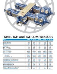
Heavy Duty Balanced Opposed Compressors
Heavy Duty Balanced Opposed Compressors
Heavy Duty Balanced Opposed Compressors

You also want an ePaper? Increase the reach of your titles
YUMPU automatically turns print PDFs into web optimized ePapers that Google loves.
FOR MODELS: JG AND JGA SECTION 4 - LUBRICATION AND VENTING<br />
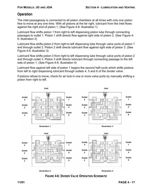
Operation<br />
The inlet passageway is connected to all piston chambers at all times with only one piston<br />
free to move at any one time. With all pistons at the far right, lubricant from the inlet flows<br />
against the right end of piston 1. (See Figure 4-6: illustration 1)<br />
Lubricant flow shifts piston 1 from right to left dispensing piston lube through connecting<br />
passages to outlet 1. Piston 1 shift directs flow against right side of piston 2. (See Figure 4-<br />
6: illustration 2)<br />
Lubricant flow shifts piston 2 from right to left dispensing lube through valve ports of piston 1<br />
and through outlet 2. Piston 2 shift directs lubricant flow against right side of piston 3. (See<br />
Figure 4-6: illustration 3)<br />
Lubricant flow shifts piston 3 from right to left dispensing lube through valve ports of piston 2<br />
and through outlet 3. Piston 3 shift directs lubricant through connecting passage to the left<br />
side of piston 1. (See Figure 4-6: illustration 4)<br />
Lubricant flow against left side of piston 1 begins the second half-cycle which shifts pistons<br />
from left to right dispensing lubricant through outlets 4, 5 and 6 of the divider valve.<br />
If pistons refuse to move, check for air lock in one or more valve ports by manually shifting a<br />
piston from right to left.<br />
Outlet<br />
4<br />
Outlet<br />
2<br />
Outlet<br />
3<br />
Outlet<br />
4<br />
Outlet<br />
2<br />
Outlet<br />
3<br />
Inlet Inlet<br />
Illustration 1 Illustration 3<br />
Inlet<br />
Outlet<br />
1<br />
Outlet<br />
5<br />
Outlet<br />
6<br />
Outlet<br />
1<br />
Outlet<br />
5<br />
Outlet<br />
6<br />
FIGURE 4-6: DIVIDER VALVE OPERATION SCHEMATIC<br />
11/01 PAGE 4 - 17<br />
Outlet<br />
4<br />
Outlet<br />
2<br />
Outlet<br />
3<br />
Outlet<br />
4<br />
Outlet<br />
2<br />
Outlet<br />
3<br />
Inlet<br />
Illustration 2 Illustration 4<br />
Outlet<br />
1<br />
Outlet<br />
5<br />
Outlet<br />
6<br />
Outlet<br />
1<br />
Outlet<br />
5<br />
Outlet<br />
6