Heavy Duty Balanced Opposed Compressors
Heavy Duty Balanced Opposed Compressors
Heavy Duty Balanced Opposed Compressors

Create successful ePaper yourself
Turn your PDF publications into a flip-book with our unique Google optimized e-Paper software.
FOR MODELS: JG AND JGA SECTION 5 - MAINTENANCE<br />
iliary end cover to the near faces of the drive sprockets on the crankshaft with a good<br />
machinist rule. Check the driven sprockets in the chain drive system against the measured<br />
dimensions at crankshaft drive sprockets. Adjust the driven sprockets to the drive sprocket<br />
measurements to be aligned within 1/32 inch (1mm).<br />
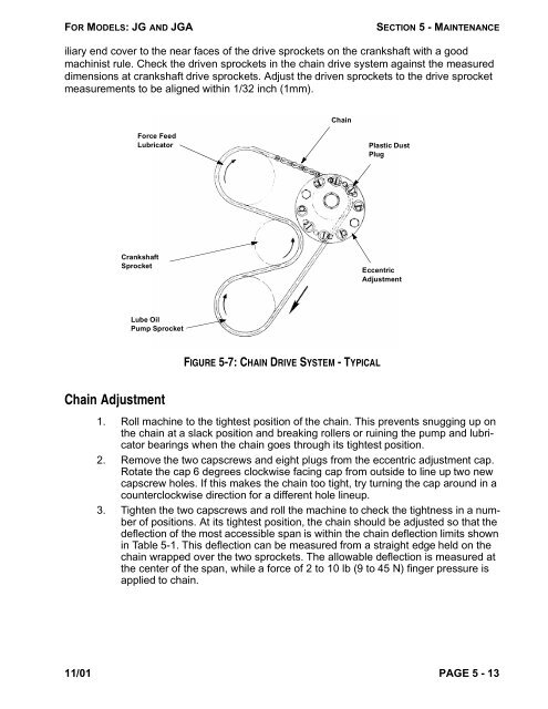
Force Feed<br />
Lubricator<br />
Crankshaft<br />
Sprocket<br />
Lube Oil<br />
Pump Sprocket<br />
Chain Adjustment<br />
FIGURE 5-7: CHAIN DRIVE SYSTEM - TYPICAL<br />
Plastic Dust<br />
Plug<br />
Eccentric<br />
Adjustment<br />
1. Roll machine to the tightest position of the chain. This prevents snugging up on<br />
the chain at a slack position and breaking rollers or ruining the pump and lubricator<br />
bearings when the chain goes through its tightest position.<br />
2. Remove the two capscrews and eight plugs from the eccentric adjustment cap.<br />
Rotate the cap 6 degrees clockwise facing cap from outside to line up two new<br />
capscrew holes. If this makes the chain too tight, try turning the cap around in a<br />
counterclockwise direction for a different hole lineup.<br />
3. Tighten the two capscrews and roll the machine to check the tightness in a number<br />
of positions. At its tightest position, the chain should be adjusted so that the<br />
deflection of the most accessible span is within the chain deflection limits shown<br />
in Table 5-1. This deflection can be measured from a straight edge held on the<br />
chain wrapped over the two sprockets. The allowable deflection is measured at<br />
the center of the span, while a force of 2 to 10 lb (9 to 45 N) finger pressure is<br />
applied to chain.<br />
11/01 PAGE 5 - 13<br />
Chain