Defining CCS Ready: An Approach to An International Definition
Defining CCS Ready: An Approach to An International Definition
Defining CCS Ready: An Approach to An International Definition
- No tags were found...

Create successful ePaper yourself
Turn your PDF publications into a flip-book with our unique Google optimized e-Paper software.
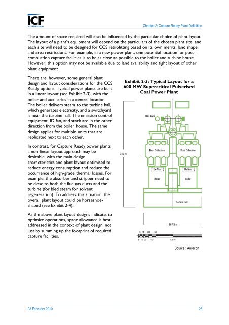
Chapter 2: Capture <strong>Ready</strong> Plant <strong>Definition</strong>The amount of space required will also be influenced by the particular choice of plant layout.The layout of a plant’s equipment will depend on the particulars of the chosen plant site, andeach site will need <strong>to</strong> be designed for <strong>CCS</strong> retrofitting based on its own merits, land shape,and area restrictions. For example, in a new power plant, one potential location for postcombustioncapture facilities is <strong>to</strong> be as close as possible <strong>to</strong> the boiler and turbine house.However, this option may not be available due <strong>to</strong> land availability and tight layout of otherplant equipmentThere are, however, some general plantdesign and layout considerations for the <strong>CCS</strong><strong>Ready</strong> options. Typical power plants are builtin a linear layout (see Exhibit 2-3), with theboiler and auxiliaries in a central location.The boiler delivers steam <strong>to</strong> the turbine hall,which generates electricity, and a switchyardis near the turbine hall. The emission controlequipment, ID fan, and stack are in the otherdirection from the boiler house. The samedesign applies for multiple units that arereplicated next <strong>to</strong> each other.Exhibit 2-3: Typical Layout for a600 MW Supercritical PulverisedCoal Power PlantIn contrast, for Capture <strong>Ready</strong> power plantsa non-linear layout approach may bedesirable, with the main designcharacteristics and plant layout optimised <strong>to</strong>reduce energy consumption and reduce theoccurrence of high-grade thermal losses. Forexample, the absorber and stripper need <strong>to</strong>be close <strong>to</strong> both the flue gas ducts and theturbine (for bled steam for solventregeneration). To address this situation, theoverall plant layout could be horseshoeshaped(see Exhibit 2-4).As the above plant layout designs indicate, <strong>to</strong>optimize operations, space allowance is bestaddressed in the context of plant design, notjust by summing up the footprint of requiredcapture facilities.Source : Aurecon23 February 2010 26