12LS Controller Installation and Operation Manual, Rev 3 ... - Watlow
12LS Controller Installation and Operation Manual, Rev 3 ... - Watlow
12LS Controller Installation and Operation Manual, Rev 3 ... - Watlow

You also want an ePaper? Increase the reach of your titles
YUMPU automatically turns print PDFs into web optimized ePapers that Google loves.
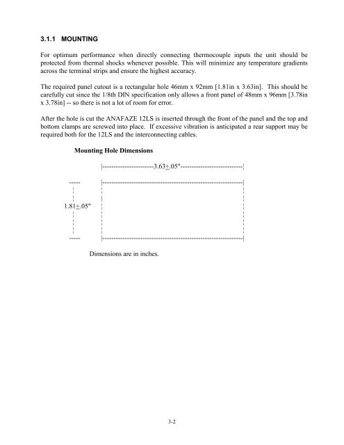
3.1.1 MOUNTINGFor optimum performance when directly connecting thermocouple inputs the unit should beprotected from thermal shocks whenever possible. This will minimize any temperature gradientsacross the terminal strips <strong>and</strong> ensure the highest accuracy.The required panel cutout is a rectangular hole 46mm x 92mm [1.81in x 3.63in]. This should becarefully cut since the 1/8th DIN specification only allows a front panel of 48mm x 96mm [3.78inx 3.78in] -- so there is not a lot of room for error.After the hole is cut the ANAFAZE <strong>12LS</strong> is inserted through the front of the panel <strong>and</strong> the top <strong>and</strong>bottom clamps are screwed into place. If excessive vibration is anticipated a rear support may berequired both for the <strong>12LS</strong> <strong>and</strong> the interconnecting cables.Mounting Hole Dimensions|-----------------------3.63+.05"----------------------------¦----- |---------------------------------------------------------------|¦ ¦ ¦¦ | ¦1.81+.05" ¦ ¦¦ ¦ ¦¦ ¦ ¦¦ ¦ ¦----- |---------------------------------------------------------------|Dimensions are in inches.3-2