12LS Controller Installation and Operation Manual, Rev 3 ... - Watlow
12LS Controller Installation and Operation Manual, Rev 3 ... - Watlow
12LS Controller Installation and Operation Manual, Rev 3 ... - Watlow
Create successful ePaper yourself
Turn your PDF publications into a flip-book with our unique Google optimized e-Paper software.
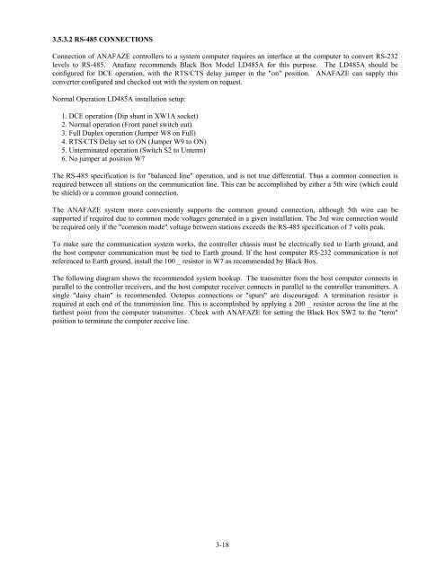
3.5.3.2 RS-485 CONNECTIONSConnection of ANAFAZE controllers to a system computer requires an interface at the computer to convert RS-232levels to RS-485. Anafaze recommends Black Box Model LD485A for this purpose. The LD485A should beconfigured for DCE operation, with the RTS/CTS delay jumper in the "on" position. ANAFAZE can supply thisconverter configured <strong>and</strong> checked out with the system on request.Normal <strong>Operation</strong> LD485A installation setup:1. DCE operation (Dip shunt in XW1A socket)2. Normal operation (Front panel switch out)3. Full Duplex operation (Jumper W8 on Full)4. RTS/CTS Delay set to ON (Jumper W9 to ON)5. Unterminated operation (Switch S2 to Unterm)6. No jumper at position W7The RS-485 specification is for "balanced line" operation, <strong>and</strong> is not true differential. Thus a common connection isrequired between all stations on the communication line. This can be accomplished by either a 5th wire (which couldbe shield) or a common ground connection.The ANAFAZE system more conveniently supports the common ground connection, although 5th wire can besupported if required due to common mode voltages generated in a given installation. The 3rd wire connection wouldbe required only if the "common mode" voltage between stations exceeds the RS-485 specification of 7 volts peak.To make sure the communication system works, the controller chassis must be electrically tied to Earth ground, <strong>and</strong>the host computer communication must be tied to Earth ground. If the host computer RS-232 communication is notreferenced to Earth ground, install the 100 _ resistor in W7 as recommended by Black Box.The following diagram shows the recommended system hookup. The transmitter from the host computer connects inparallel to the controller receivers, <strong>and</strong> the host computer receiver connects in parallel to the controller transmitters. Asingle "daisy chain" is recommended. Octopus connections or "spurs" are discouraged. A termination resistor isrequired at each end of the transmission line. This is accomplished by applying a 200 _ resistor across the line at thefarthest point from the computer transmitter. Check with ANAFAZE for setting the Black Box SW2 to the "term"position to terminate the computer receive line.3-18


