- Page 1 and 2:
Alibre DesignUser Guide9.1
- Page 3 and 4:
ContentsInstallation...............
- Page 5 and 6:
4.8 Working in a Sketch............
- Page 7 and 8:
7.6.1 Sweep Boss and Sweep Cut Feat
- Page 9 and 10:
10.3.1 Inserting Configurations of
- Page 11 and 12:
12.5.3 Detail View ................
- Page 13 and 14:
15.9 Viewing an Item's Version Hist
- Page 15:
19.5 Forces and Torques In Simulati
- Page 18 and 19:
Chapter 1 - Installation1.1 System
- Page 20 and 21:
Chapter 1 - Installation• SprutCA
- Page 22 and 23:
Chapter 1 - Installation1.5 Install
- Page 24 and 25:
Chapter 2 - Getting Started With Al
- Page 26 and 27:
Chapter 2 - Getting Started With Al
- Page 28 and 29:
Chapter 2 - Getting Started With Al
- Page 30 and 31:
Chapter 2 - Getting Started With Al
- Page 32 and 33:
Chapter 2 - Getting Started With Al
- Page 34 and 35:
Chapter 2 - Getting Started With Al
- Page 36 and 37:
Chapter 2 - Getting Started With Al
- Page 38 and 39:
Chapter 2 - Getting Started With Al
- Page 40 and 41:
Chapter 2 - Getting Started With Al
- Page 42 and 43:
Chapter 2 - Getting Started With Al
- Page 44 and 45:
Chapter 2 - Getting Started With Al
- Page 46 and 47:
Chapter 3 - Introduction to the Des
- Page 48 and 49:
Chapter 3 - Introduction to the Des
- Page 50 and 51:
Chapter 3 - Introduction to the Des
- Page 52 and 53:
Chapter 3 - Introduction to the Des
- Page 54 and 55:
Chapter 3 - Introduction to the Des
- Page 56 and 57:
Chapter 3 - Introduction to the Des
- Page 58 and 59:
Chapter 3 - Introduction to the Des
- Page 60 and 61:
Chapter 3 - Introduction to the Des
- Page 62 and 63:
Chapter 3 - Introduction to the Des
- Page 64 and 65:
Chapter 3 - Introduction to the Des
- Page 66 and 67:
Chapter 4 - Sketching4.1 The Sketch
- Page 68 and 69:
Chapter 4 - SketchingOrFrom the Ske
- Page 70 and 71:
Chapter 4 - Sketching‣ To move a
- Page 72 and 73:
Chapter 4 - Sketching‣ To sketch
- Page 74 and 75:
Chapter 4 - Sketching2. Select the
- Page 76 and 77:
Chapter 4 - Sketching1. Select the
- Page 78 and 79:
Chapter 4 - Sketching• Dragging a
- Page 80 and 81:
Chapter 4 - Sketching‣ To resize
- Page 82 and 83:
Chapter 4 - Sketching5. Choose Appl
- Page 84 and 85:
Chapter 4 - SketchingStandard Shape
- Page 86 and 87:
Chapter 4 - SketchingYou will set t
- Page 88 and 89:
Chapter 4 - SketchingWhen Circular
- Page 90 and 91:
Chapter 4 - SketchingExamples of tw
- Page 92 and 93:
Chapter 4 - SketchingThe Shape dial
- Page 94 and 95:
Chapter 4 - Sketching4. Set the Fir
- Page 96 and 97:
Chapter 4 - Sketching4.5.2 Trimming
- Page 98 and 99:
Chapter 4 - Sketching3. Select the
- Page 100 and 101:
Chapter 4 - Sketching4.5.7 Creating
- Page 102 and 103:
Chapter 4 - Sketching2. Select the
- Page 104 and 105:
Chapter 4 - Sketching3. Hold the Sh
- Page 106 and 107:
Chapter 4 - SketchingFixed - Figure
- Page 108 and 109:
Chapter 4 - Sketching3. In the sket
- Page 110 and 111:
Chapter 4 - SketchingWell-defined:
- Page 112 and 113:
Chapter 4 - SketchingTwo types of d
- Page 114 and 115:
Chapter 4 - Sketching3. Click the f
- Page 116 and 117:
Chapter 4 - Sketching‣ To auto di
- Page 118 and 119:
Chapter 4 - Sketching‣ To use the
- Page 120 and 121:
Chapter 4 - Sketchingsin(x) sine Re
- Page 122 and 123:
Chapter 4 - Sketching2. Move the cu
- Page 124 and 125:
Chapter 4 - SketchingThe grid acts
- Page 126 and 127:
Chapter 4 - SketchingFrom the View
- Page 128 and 129:
Chapter 4 - Sketching2. Right-click
- Page 130 and 131:
Chapter 4 - Sketching2. Select eith
- Page 132 and 133:
Chapter 4 - Sketching4. Exit sketch
- Page 135 and 136:
Chapter 5 - 3D SketchingC HAPTER 53
- Page 137 and 138:
Chapter 5 - 3D Sketching5.1.1 3D Sk
- Page 139 and 140:
Chapter 5 - 3D Sketching‣ To turn
- Page 141 and 142:
Chapter 5 - 3D SketchingWhile in a
- Page 143 and 144:
Chapter 5 - 3D Sketching‣ To exit
- Page 145 and 146:
Chapter 5 - 3D Sketching‣ To sket
- Page 147 and 148:
Chapter 5 - 3D Sketching5.4.2 Inser
- Page 149 and 150:
Chapter 5 - 3D SketchingLinear, rad
- Page 151 and 152:
Chapter 5 - 3D Sketching4. After th
- Page 153 and 154:
Chapter 5 - 3D SketchingDuring the
- Page 155 and 156:
Chapter 6 - Reference GeometryC HAP
- Page 157 and 158:
Chapter 6 - Reference Geometry4. Cl
- Page 159 and 160:
Chapter 6 - Reference Geometry6.1.4
- Page 161 and 162:
Chapter 6 - Reference Geometry6.2 A
- Page 163 and 164:
Chapter 6 - Reference Geometry2. Se
- Page 165 and 166:
Chapter 6 - Reference Geometry6.3.6
- Page 167 and 168:
Chapter 6 - Reference Geometry‣ T
- Page 169 and 170:
Chapter 6 - Reference Geometry‣ T
- Page 171:
Chapter 6 - Reference Geometry6.6 R
- Page 174 and 175:
Chapter 7 - Feature Creation7.1 The
- Page 176 and 177:
Chapter 7 - Feature CreationCutCut
- Page 178 and 179:
Chapter 7 - Feature Creationc. To c
- Page 180 and 181:
Chapter 7 - Feature Creation7.3.2 C
- Page 182 and 183:
Chapter 7 - Feature Creation7.4.1 R
- Page 184 and 185:
Chapter 7 - Feature Creation3. Sele
- Page 186 and 187:
Chapter 7 - Feature Creation5. If S
- Page 188 and 189:
Chapter 7 - Feature CreationLoft Us
- Page 190 and 191:
Chapter 7 - Feature Creation4. In t
- Page 192 and 193:
Chapter 7 - Feature Creation3. From
- Page 194 and 195:
Chapter 7 - Feature CreationHelical
- Page 196 and 197:
Chapter 7 - Feature Creation• Hei
- Page 198 and 199:
Chapter 7 - Feature Creation7.8.1 C
- Page 200 and 201:
Chapter 7 - Feature Creation7.9 Cha
- Page 202 and 203:
Chapter 7 - Feature Creation4. Clic
- Page 204 and 205:
Chapter 7 - Feature Creation‣ To
- Page 206 and 207:
Chapter 7 - Feature Creation8. Clic
- Page 208 and 209:
Chapter 7 - Feature Creation7.13.2
- Page 210 and 211:
Chapter 7 - Feature Creation5. Clic
- Page 212 and 213:
Chapter 7 - Feature Creation4. Sele
- Page 214 and 215:
Chapter 7 - Feature Creation7.15 De
- Page 216 and 217:
Chapter 7 - Feature Creation• Boo
- Page 218 and 219:
Chapter 7 - Feature Creation‣ To
- Page 221 and 222:
Chapter 8 - Sheet Metal Feature Cre
- Page 223 and 224:
Chapter 8 - Sheet Metal Feature Cre
- Page 225 and 226:
Chapter 8 - Sheet Metal Feature Cre
- Page 227 and 228:
Chapter 8 - Sheet Metal Feature Cre
- Page 229 and 230:
Chapter 8 - Sheet Metal Feature Cre
- Page 231 and 232:
Chapter 8 - Sheet Metal Feature Cre
- Page 233 and 234:
Chapter 8 - Sheet Metal Feature Cre
- Page 235 and 236:
Chapter 8 - Sheet Metal Feature Cre
- Page 237:
Chapter 8 - Sheet Metal Feature Cre
- Page 240 and 241:
Chapter 9 - Working with Parts9.1 S
- Page 242 and 243:
Chapter 9 - Working with Parts‣ T
- Page 244 and 245:
Chapter 9 - Working with Parts‣ T
- Page 246 and 247:
Chapter 9 - Working with PartsThe F
- Page 248 and 249:
Chapter 9 - Working with PartsNote:
- Page 250 and 251:
Chapter 9 - Working with Parts5. Cl
- Page 252 and 253:
Chapter 9 - Working with Parts5. To
- Page 254 and 255:
Chapter 9 - Working with Parts9.10.
- Page 256 and 257:
Chapter 9 - Working with Parts10. I
- Page 258 and 259:
Chapter 9 - Working with Parts8. In
- Page 260 and 261:
Chapter 9 - Working with Parts6. In
- Page 262 and 263:
Chapter 9 - Working with Parts‣ T
- Page 264 and 265:
Chapter 9 - Working with PartsExplo
- Page 266 and 267:
Chapter 9 - Working with Parts9.13
- Page 268 and 269:
Chapter 9 - Working with Parts9.16
- Page 271 and 272:
Chapter 10 - Design ConfigurationsC
- Page 273 and 274:
Chapter 10 - Design ConfigurationsC
- Page 275 and 276:
Chapter 10 - Design ConfigurationsP
- Page 277 and 278:
Chapter 10 - Design ConfigurationsI
- Page 279 and 280:
Chapter 10 - Design ConfigurationsT
- Page 281 and 282: Chapter 10 - Design Configurations
- Page 283 and 284: Chapter 10 - Design ConfigurationsT
- Page 285 and 286: Chapter 10 - Design ConfigurationsP
- Page 287 and 288: Chapter 10 - Design Configurations1
- Page 289 and 290: Chapter 10 - Design ConfigurationsN
- Page 291 and 292: Chapter 10 - Design ConfigurationsN
- Page 293 and 294: Chapter 10 - Design ConfigurationsT
- Page 295 and 296: Chapter 10 - Design ConfigurationsE
- Page 297 and 298: Chapter 10 - Design ConfigurationsT
- Page 299 and 300: Chapter 10 - Design ConfigurationsT
- Page 301: Chapter 10 - Design ConfigurationsF
- Page 304 and 305: Chapter 11 - Assembly Design11.1 As
- Page 306 and 307: Chapter 11 - Assembly DesignInsert
- Page 308 and 309: Chapter 11 - Assembly DesignFile Sy
- Page 310 and 311: Chapter 11 - Assembly Design‣ To
- Page 312 and 313: Chapter 11 - Assembly Design3. In R
- Page 314 and 315: Chapter 11 - Assembly DesignThe cir
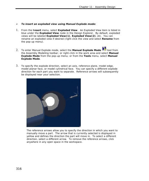
- Page 316 and 317: Chapter 11 - Assembly Design4. Clic
- Page 318 and 319: Chapter 11 - Assembly Design‣ To
- Page 320 and 321: Chapter 11 - Assembly DesignSphere
- Page 322 and 323: Chapter 11 - Assembly Design11.4.3
- Page 324 and 325: Chapter 11 - Assembly Design‣ To
- Page 326 and 327: Chapter 11 - Assembly DesignIn the
- Page 328 and 329: Chapter 11 - Assembly Design‣ To
- Page 330 and 331: Chapter 11 - Assembly Design‣ To
- Page 334 and 335: Chapter 11 - Assembly Design9. To a
- Page 336 and 337: Chapter 11 - Assembly DesignYou mus
- Page 338 and 339: Chapter 11 - Assembly Design2. You
- Page 340 and 341: Chapter 11 - Assembly Design‣ To
- Page 342 and 343: Chapter 11 - Assembly DesignAdditio
- Page 344 and 345: Chapter 11 - Assembly DesignThe par
- Page 346 and 347: Chapter 11 - Assembly Design‣ To
- Page 349 and 350: Chapter 12 - DrawingsC HAPTER 12Dra
- Page 351 and 352: Chapter 12 - Drawings12.1.3 Specify
- Page 353 and 354: Chapter 12 - Drawings3. In the View
- Page 355 and 356: Chapter 12 - Drawings5. If desired,
- Page 357 and 358: Chapter 12 - Drawings12.3 Working i
- Page 359 and 360: Chapter 12 - Drawings12.3.2 Renamin
- Page 361 and 362: Chapter 12 - Drawings• Annotation
- Page 363 and 364: Chapter 12 - DrawingsA sheet bounda
- Page 365 and 366: Chapter 12 - Drawings‣ To show or
- Page 367 and 368: Chapter 12 - DrawingsNote: To inser
- Page 369 and 370: Chapter 12 - Drawings• Locked [ch
- Page 371 and 372: Chapter 12 - Drawings‣ To add a l
- Page 373 and 374: Chapter 12 - Drawings‣ To add a s
- Page 375 and 376: Chapter 12 - Drawings2. Click Look
- Page 377 and 378: Chapter 12 - DrawingsYou can also m
- Page 379 and 380: Chapter 12 - Drawings5. Select the
- Page 381 and 382: Chapter 12 - Drawings‣ To change
- Page 383 and 384:
Chapter 12 - DrawingsUsing Dimensio
- Page 385 and 386:
Chapter 12 - Drawings2. Select a li
- Page 387 and 388:
Chapter 12 - Drawings5. Move the cu
- Page 389 and 390:
Chapter 12 - Drawings12.5.4 Section
- Page 391 and 392:
Chapter 12 - Drawings‣ To create
- Page 393 and 394:
Chapter 12 - Drawings‣ To change
- Page 395 and 396:
Chapter 12 - Drawings8. Click OK. T
- Page 397 and 398:
Chapter 12 - Drawings‣ To change
- Page 399 and 400:
Chapter 12 - Drawings1. Select the
- Page 401 and 402:
Chapter 12 - Drawings4. If the Fill
- Page 403 and 404:
Chapter 12 - Drawings5. Click in th
- Page 405 and 406:
Chapter 12 - Drawings12.7.1 NoteYou
- Page 407 and 408:
Chapter 12 - DrawingsThe default ca
- Page 409 and 410:
Chapter 12 - Drawings2. Right-click
- Page 411 and 412:
Chapter 12 - DrawingsThe top area o
- Page 413 and 414:
Chapter 12 - Drawings(M) MMC-maximu
- Page 415 and 416:
Chapter 12 - Drawings7. Repeat step
- Page 417 and 418:
Chapter 12 - Drawings14. Note: The
- Page 419 and 420:
Chapter 13 - Bills of MaterialC HAP
- Page 421 and 422:
Chapter 13 - Bills of Material13.2
- Page 423 and 424:
Chapter 13 - Bills of Material13.2.
- Page 425 and 426:
Chapter 13 - Bills of Material2. Th
- Page 427 and 428:
Chapter 13 - Bills of Material‣ T
- Page 429 and 430:
Chapter 13 - Bills of Material‣ T
- Page 431 and 432:
Chapter 13 - Bills of Material13.3.
- Page 433 and 434:
Chapter 13 - Bills of Material2. Th
- Page 435 and 436:
Chapter 13 - Bills of Material13.4
- Page 437 and 438:
Chapter 13 - Bills of Material4. To
- Page 439 and 440:
Chapter 13 - Bills of Material‣ T
- Page 441 and 442:
Chapter 13 - Bills of Material2. Ri
- Page 443 and 444:
Chapter 13 - Bills of Material2. Ri
- Page 445 and 446:
Chapter 13 - Bills of Material3. Cl
- Page 447 and 448:
Chapter 13 - Bills of Material‣ T
- Page 449:
Chapter 13 - Bills of Material‣ T
- Page 452 and 453:
Chapter 14 - Importing and Exportin
- Page 454 and 455:
Chapter 14 - Importing and Exportin
- Page 456 and 457:
Chapter 14 - Importing and Exportin
- Page 458 and 459:
Chapter 14 - Importing and Exportin
- Page 461 and 462:
Chapter 15 - The RepositoryC HAPTER
- Page 463 and 464:
Chapter 15 - The Repository15.2.1 C
- Page 465 and 466:
Chapter 15 - The Repository15.2.4 R
- Page 467 and 468:
Chapter 15 - The Repository• Vers
- Page 469 and 470:
Chapter 15 - The Repository4. An Ot
- Page 471 and 472:
Chapter 15 - The Repository15.6.3 R
- Page 473 and 474:
Chapter 15 - The Repository15.10 Ro
- Page 475 and 476:
Chapter 15 - The Repository15.13.1
- Page 477 and 478:
Chapter 15 - The Repository‣ To r
- Page 479 and 480:
Chapter 15 - The Repository2. Right
- Page 481 and 482:
Chapter 15 - The Repository3. Click
- Page 483 and 484:
Chapter 15 - The Repository‣ To c
- Page 485 and 486:
Chapter 15 - The Repository2. Right
- Page 487:
Chapter 15 - The Repository15.21.3
- Page 490 and 491:
Chapter 16 - The Message Center16.1
- Page 492 and 493:
Chapter 16 - The Message Center16.3
- Page 494 and 495:
Chapter 16 - The Message Center5. C
- Page 496 and 497:
Chapter 16 - The Message Center‣
- Page 498 and 499:
Chapter 17 - The Team Manager17.1 O
- Page 500 and 501:
Chapter 17 - The Team ManagerNote:
- Page 502 and 503:
Chapter 17 - The Team Managera. Exp
- Page 504 and 505:
Chapter 18 - Team Design Sessions18
- Page 506 and 507:
Chapter 18 - Team Design Sessions18
- Page 508 and 509:
Chapter 18 - Team Design Sessions
- Page 510 and 511:
Chapter 18 - Team Design Sessions4.
- Page 512 and 513:
Chapter 18 - Team Design Sessions
- Page 514 and 515:
Chapter 18 - Team Design Sessions18
- Page 516 and 517:
Chapter 18 - Team Design Sessions18
- Page 518 and 519:
Chapter 18 - Team Design Sessions
- Page 520 and 521:
Chapter 18 - Team Design SessionsUs
- Page 522 and 523:
Chapter 18 - Team Design SessionsTa
- Page 524 and 525:
Chapter 18 - Team Design SessionsNo
- Page 526 and 527:
Chapter 18 - Team Design SessionsSa
- Page 528 and 529:
Chapter 18 - Team Design Sessions18
- Page 530 and 531:
Chapter 18 - Team Design Sessions18
- Page 532 and 533:
Chapter 18 - Team Design Sessions2.
- Page 535 and 536:
Chapter 19 - Alibre MotionC HAPTER
- Page 537 and 538:
Chapter 19 - Alibre Motion19.2 Inst
- Page 539 and 540:
Chapter 19 - Alibre MotionRegenerat
- Page 541 and 542:
Chapter 19 - Alibre MotionFixed Par
- Page 543 and 544:
Chapter 19 - Alibre Motionb. frame
- Page 545 and 546:
Chapter 19 - Alibre MotionTraces Ta
- Page 547 and 548:
Chapter 19 - Alibre Motion‣ To se
- Page 549 and 550:
Chapter 19 - Alibre MotionStep Forw
- Page 551 and 552:
Chapter 19 - Alibre MotionForces Ex
- Page 553 and 554:
Chapter 19 - Alibre MotionLinear or
- Page 555 and 556:
Chapter 19 - Alibre Motion‣ To Re
- Page 557 and 558:
Chapter 19 - Alibre Motion• Ampli
- Page 559 and 560:
Chapter 19 - Alibre MotionActuator
- Page 561 and 562:
Chapter 19 - Alibre Motion19.5.3 Sp
- Page 563 and 564:
Chapter 19 - Alibre MotionNote: Dep
- Page 565 and 566:
Chapter 19 - Alibre Motion‣ To Ch
- Page 567 and 568:
Chapter 19 - Alibre MotionKinematic
- Page 569 and 570:
Chapter 19 - Alibre MotionMost cons
- Page 571 and 572:
Chapter 19 - Alibre Motion3. In Cop
- Page 573 and 574:
Chapter 19 - Alibre Motion• AVI G
- Page 575 and 576:
Chapter 19 - Alibre Motion19.7 Resu
- Page 577 and 578:
Chapter 19 - Alibre MotionSame opti
- Page 579 and 580:
Chapter 19 - Alibre MotionCurrent V
- Page 581 and 582:
Chapter 19 - Alibre MotionThe Codec
- Page 583 and 584:
Chapter 19 - Alibre Motion1. In Vid
- Page 585 and 586:
Chapter 19 - Alibre MotionResults s
- Page 587:
Chapter 19 - Alibre Motion• Does
- Page 590 and 591:
IndexAxis • 32creation methods
- Page 592 and 593:
IndexDesign Explorer • 25, 30, 36
- Page 594 and 595:
IndexHiding Individual ReferenceGeo
- Page 596 and 597:
IndexMoving and Rotating SketchFigu
- Page 598 and 599:
Indexsecurity • 464sharing and un
- Page 600 and 601:
IndexTTab • 209Tab feature • 20