MEP-Technical Manual CDN 0408.qxd - Hambro
MEP-Technical Manual CDN 0408.qxd - Hambro
MEP-Technical Manual CDN 0408.qxd - Hambro

Create successful ePaper yourself
Turn your PDF publications into a flip-book with our unique Google optimized e-Paper software.
4<br />
DESIGN PRINCIPLES AND CALCULATIONS<br />
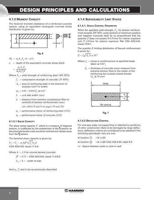
4.1.3 MOMENT CAPACITY<br />
The factored moment resistance of a reinforced concrete<br />
section, using an equivalent rectangular concrete stress<br />
distribution is given by:<br />
t<br />
d<br />
Mr = øsAs Fy (d - a/2)<br />
a = depth of the equivalent concrete stress block<br />
= ø s A s F y<br />
� 1 ø c f’ c b<br />
Where Fy = yield strength of reinforcing steel (400 MPa)<br />
f’ c = compressive strength of concrete (20 MPa)<br />
As = area of reinforcing steel in the direction of<br />
analysis (mm2 /m width)<br />
�1 = 0.85 - 0.0015f’ c ≥ 0.67<br />
b = unit slab width (mm)<br />
d = distance from extreme compression fiber to<br />
centroïd of tension reinforcement (mm)<br />
(see tables 8 and 9 on pages 19 and 20)<br />
øs = performance factor of reinforcing steel (0.85)<br />
øc = performance factor of concrete (0.65)<br />
4.1.3.1 SHEAR CAPACITY<br />
The shear stress capacity V, which is a measure of diagonal<br />
tension, is unaffected by the embedment of the section as<br />
this principal tensile crack would be inclined and radiate away<br />
from the section.<br />
The factored shear capacity is given by:<br />
Vr = Vc = øc�ß f’ c bwd √<br />
(CSA A23.3-04, clause 11.3.4)<br />
Fig. 6<br />
c C<br />
Where � = 1.0 for normal density concrete<br />
ß = 0.21 = (CSA A23.3-04, clause 11.3.6.3)<br />
bw = b = width of slab<br />
And ø c ,f’ c and d are as previously described.<br />
T<br />
a<br />
4.1.4 SERVICEABILITY LIMIT STATES<br />
4.1.4.1. CRACK CONTROL PARAMETER<br />
When the specified yield strength, F y , for tension reinforcement<br />
exceeds 300 MPa, cross sections of maximum positive<br />
and negative moments shall be so proportioned that the<br />
quantity Z does not exceed 30 kN/mm for interior exposure<br />
and 25 kN/mm for exterior exposure. Ref. CSA A23.3-04,<br />
clause 10.6.1.<br />
The quantity Z limiting distribution of flexural reinforcement<br />
is given by:<br />
3<br />
Z = fs dcA x 10-3 √<br />
Where fs = stress in reinforcement at specified loads<br />
taken as 0.6Fy dc = thickness of concrete cover measure from<br />
extreme tension fibre to the center of the<br />
reinforcing bar located closest thereto<br />
(dc ≤ 50 mm)<br />
4.1.4.2 DEFLECTION CONTROL<br />
For one-way slabs not supporting or attached to partitions<br />
of other construction likely to be damaged by large deflections,<br />
deflection criteria are considered to be satisfied if the<br />
following span/depth ratio are met:<br />
at location � t ≥ �n/24<br />
Width<br />
Bar spacing<br />
Fig. 7<br />
at location � t ≥ �n/28 (CSA A23.3-04, table 9.2)<br />
�n=Space between joists or joist to wall<br />
d c<br />
d c