MEP-Technical Manual CDN 0408.qxd - Hambro
MEP-Technical Manual CDN 0408.qxd - Hambro
MEP-Technical Manual CDN 0408.qxd - Hambro

Create successful ePaper yourself
Turn your PDF publications into a flip-book with our unique Google optimized e-Paper software.
DESIGN PRINCIPLES AND CALCULATIONS<br />
4.6 DIAPHRAGM DESIGN<br />
4.6.1 THE HAMBRO SLAB AS A DIAPHRAGM<br />
With the increasing use of the <strong>Hambro</strong> system for floor of<br />
buildings in earthquake prone areas such as Anchorage,<br />
Los Angeles, Vancouver, Montreal and Quebec City or in<br />
hurricane prone areas such as Florida as well as for multistorey<br />
buildings where shear transfer could occur at some<br />
level of the building due to the reduction of the floor plan,<br />
it is important to develop an understanding of how the<br />
slabs will be able to transmit horizontal loads while being<br />
part of the <strong>Hambro</strong> floor system.<br />
The floor slab, part of the <strong>Hambro</strong> system, must be designed<br />
by the project structural engineer as a diaphragm to resist<br />
horizontal loads and transmit them to the vertical bracing<br />
system.<br />
Any diaphragm has the following limit states:<br />
1) Shear strength between the supports<br />
2) Out of plane buckling<br />
3) In plane deflection of the diaphragm<br />
4) Shear transmission at the supports<br />
A diaphragm works as the web of a beam spanning<br />
between or extending beyond the supports. In the case of<br />
a floor slab, the slab is the web of the beam spanning<br />
between or extending beyond the vertical elements<br />
designed to transmit to the foundations the horizontal<br />
loads produced by earthquake or wind.<br />
We will use a simple example of wind load acting on a<br />
diaphragm part of a horizontal beam forming a single span<br />
between end walls. The structural engineer responsible for<br />
the design of the building shall establish the horizontal<br />
loads that must be resisted at each floor of the building for<br />
the wind and earthquake conditions prevailing at the building<br />
location. The structural engineer must also identify the<br />
vertical elements that will transmit the horizontal loads to<br />
the foundations in order to calculate the shear that must be<br />
resisted by the floor slab.<br />
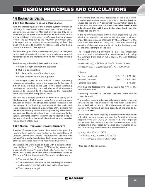
4.6.2 SHEAR STRENGTH BETWEEN SUPPORTS<br />
A series of fourteen specimens of concrete slabs, part of a<br />
<strong>Hambro</strong> floor system, were tested in the laboratories of<br />
Carleton University in Ottawa. The purpose of the tests was<br />
to identify the variables affecting the in plane shear strength<br />
of the concrete slab reinforced with welded wire mesh.<br />
The specimens were made of slabs with a concrete thickness<br />
of 63 mm (2.5”) or 70 mm (2.75”) forming a beam with<br />
a span of 610 mm (24”) and a depth of 610 mm (24”). This<br />
beam was loaded with two equal concentrated loads at<br />
152 mm (6”) from the supports. The other variables were:<br />
1) The size of the wire mesh<br />
2) The presence or absence of the <strong>Hambro</strong> joist embedded<br />
top chord parallel to the load in the shear zone<br />
3) The concrete strength<br />
It was found that the shear resistance of the slab is minimized<br />
when the shear stress is parallel to the <strong>Hambro</strong> joist<br />
embedded top chord. A conservative assumption could be<br />
made that the concrete confined steel wire mesh is the<br />
only element that will transmit the shear load over the<br />
embedded top chord.<br />
In the following example of the design procedure, we will<br />
take into account that the steel of the wire mesh is already<br />
under tension stresses produced by the continuity of the<br />
slab over the <strong>Hambro</strong> joist, and that the remaining<br />
capacity of the steel wire mesh will be the limiting factor<br />
for the shear strength of the slab.<br />
The largest bending moment is over the embedded<br />
top chord and is calculated for one meter width. In using<br />
the example from section 4.1.5 page 5, the non factored<br />
moment is:<br />
Dead load*: Mfd = 3KPa x (1.2m) 2 / 10 = 0.43 kN•m<br />
Live load*: MfL = 2KPa x (1.2m) 2 / 10 = 0.29 kN•m.<br />
1) Loads<br />
Factored dead load: 1.25 x 3.0 = 3.75 kPa<br />
Factored live load: 1.50 x 2.0 = 3.00 kPa<br />
Factored total load: 6.75 kPa<br />
And thus the factored live load accounts for 44% of the<br />
factored total load.<br />
2) Bending moment in the slab between joists due to<br />
gravity loads<br />
The smallest lever arm between the compression concrete<br />
surface and the tension steel of the wire mesh is also over<br />
the embedded top chord. This dimension allows us to<br />
calculate the factored bending capacity of the slab to be<br />
Mr = 1.61 kN•m*.<br />
To establish the shear capacity of steel wire mesh for a slab<br />
unit width of one meter, we use the following formula<br />
adapted from CSA A23.3-04 clause 11.5 and simplified<br />
to calculate the resistance of the reinforcing steel only,<br />
considering a shear crack developing at a 45 degree angle<br />
and intersecting the wire mesh in both directions.<br />
V r = ø s x A s x F y x cos (45°)<br />
= 0.85 x 2 x 123 x 400 x 0.707/1 000<br />
= 59.1 kN for a meter width of slab<br />
* See page 5 for calculation.<br />
15