MEP-Technical Manual CDN 0408.qxd - Hambro
MEP-Technical Manual CDN 0408.qxd - Hambro
MEP-Technical Manual CDN 0408.qxd - Hambro

You also want an ePaper? Increase the reach of your titles
YUMPU automatically turns print PDFs into web optimized ePapers that Google loves.
DESIGN PRINCIPLES AND CALCULATIONS<br />
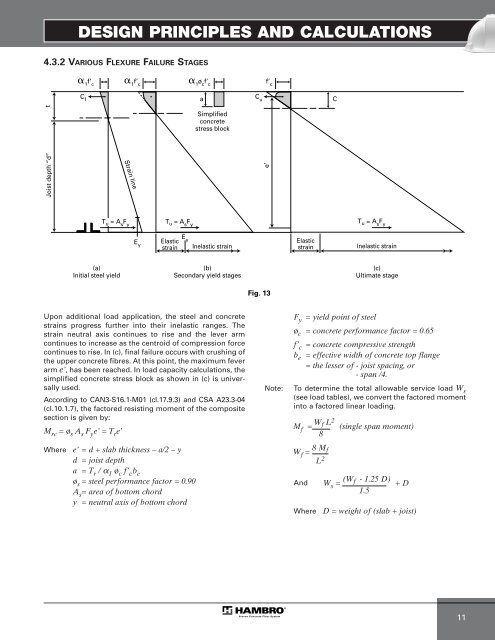
4.3.2 VARIOUS FLEXURE FAILURE STAGES<br />
t<br />
Joist depth “d”<br />
� 1 f’ c<br />
C f a<br />
Upon additional load application, the steel and concrete<br />
strains progress further into their inelastic ranges. The<br />
strain neutral axis continues to rise and the lever arm<br />
continues to increase as the centroid of compression force<br />
continues to rise. In (c), final failure occurs with crushing of<br />
the upper concrete fibres. At this point, the maximum fever<br />
arm e’, has been reached. In load capacity calculations, the<br />
simplified concrete stress block as shown in (c) is universally<br />
used.<br />
According to CAN3-S16.1-M01 (cl.17.9.3) and CSA A23.3-04<br />
(cl.10.1.7), the factored resisting moment of the composite<br />
section is given by:<br />
M rc = ø s A s F y e’ = T r e’<br />
Strain line<br />
T u = A s F y<br />
(a)<br />
Initial steel yield<br />
� 1 f’ c<br />
Where e’ = d + slab thickness – a/2 – y<br />
d = joist depth<br />
a = T r / � 1 ø c f’ c b e<br />
ø s = steel performance factor = 0.90<br />
A s = area of bottom chord<br />
y = neutral axis of bottom chord<br />
E y<br />
T u = A s F y<br />
Elastic<br />
strain<br />
E y<br />
� 1 ø c f’ c<br />
Simplified<br />
concrete<br />
stress block<br />
Inelastic strain<br />
(b)<br />
Secondary yield stages<br />
C u<br />
f’ c<br />
e’<br />
Fig. 13<br />
Elastic<br />
strain<br />
Fy = yield point of steel<br />
øc = concrete performance factor = 0.65<br />
f’ c = concrete compressive strength<br />
be = effective width of concrete top flange<br />
= the lesser of - joist spacing, or<br />
- span /4.<br />
Note: To determine the total allowable service load W s<br />
(see load tables), we convert the factored moment<br />
into a factored linear loading.<br />
Mf = Wf L2 (single span moment)<br />
8<br />
W f = 8 M f<br />
L 2<br />
And<br />
C<br />
T u = A s F y<br />
Inelastic strain<br />
(c)<br />
Ultimate stage<br />
W s = (W f - 1.25 D) + D<br />
1.5<br />
Where D = weight of (slab + joist)<br />
11