MEP-Technical Manual CDN 0408.qxd - Hambro
MEP-Technical Manual CDN 0408.qxd - Hambro
MEP-Technical Manual CDN 0408.qxd - Hambro

Create successful ePaper yourself
Turn your PDF publications into a flip-book with our unique Google optimized e-Paper software.
DESIGN PRINCIPLES AND CALCULATIONS<br />
4. DESIGN PRINCIPLES AND CALCULATIONS<br />
4.1 SLAB DESIGN<br />
4.1.1 THE HAMBRO SLAB<br />
The slab component of the <strong>Hambro</strong> Composite Floor System<br />
behaves as a continuous one-way slab carrying loads<br />
transversely to the joists, and often is required to also act<br />
as a diaphragm carrying lateral loads to shear walls or<br />
other lateral load resisting elements.<br />
The slab design is based on CSA Standard A23.3-04, Design<br />
of Concrete Structures which stipulates that in order to<br />
provide adequate safety level, the factored effects shall be<br />
less than the factored resistance.<br />
� S ≤ ø R<br />
Where � = load factor, taking into account the probability<br />
of exceeding the specified load<br />
S = load effect (dead or live)<br />
ø = performance factor<br />
R = member resistance<br />
4.1.2. EFFECTS OF LOADING<br />
The Canadian concrete code (CSA Standard A23.3-04)<br />
cl. 9.2.3.1. requires that we consider dead load to act simultaneously<br />
with the live load applied on:<br />
i) Adjacent spans (maximum negative moment at support)<br />
or<br />
ii) Alternate spans (maximum positive moment at mid-span).<br />
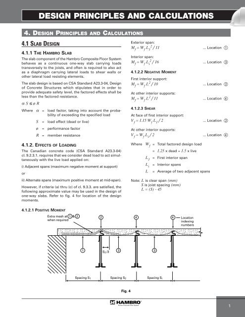
However, if criteria (a) thru (c) of cl. 9.3.3. are satisfied, the<br />
following approximate value may be used in the design of<br />
one-way slabs. Refer to fig. 4 for location of the design<br />
moments.<br />
4.1.2.1 POSITIVE MOMENT<br />
Extra mesh at 1 & 2<br />
when required<br />
1<br />
Spacing S1<br />
S2 /3<br />
Spacing S2<br />
Fig. 4<br />
Exterior span:<br />
M f = W f L 1 2 / 11 ... Location �<br />
Interior span:<br />
M f = W f L i 2 / 16 ... Location �<br />
4.1.2.2 NEGATIVE MOMENT<br />
First interior support:<br />
Mf = Wf L2 / 10 ... Location �<br />
At other interior supports:<br />
M f = W f L 2 / 11 ... Location �<br />
4.1.2.3 SHEAR<br />
At face of first interior support:<br />
Vf = 1.15 Wf L1 / 2 ... Location �<br />
At other interior supports:<br />
V f = W f L i / 2 ... Location �<br />
Where W f = Total factored design load<br />
= 1.25 x dead + 1.5 x live<br />
L1 = First interior span<br />
Li = Interior spans<br />
L = Average of two adjacent spans<br />
Note: L is clear span (mm)<br />
S is joist spacing (mm)<br />
L = (S) - 45<br />
2 4<br />
4 Location<br />
indexing<br />
numbers<br />
3 3<br />
Spacing Si<br />
1