MEP-Technical Manual CDN 0408.qxd - Hambro
MEP-Technical Manual CDN 0408.qxd - Hambro
MEP-Technical Manual CDN 0408.qxd - Hambro

Create successful ePaper yourself
Turn your PDF publications into a flip-book with our unique Google optimized e-Paper software.
8<br />
DESIGN PRINCIPLES AND CALCULATIONS<br />
4.2 NON-COMPOSITE DESIGN<br />
2<br />
D<br />
Y<br />
Fig. 8<br />
N.A. of top chord<br />
The top chord must be verified for the loads applied at the<br />
non-composite stage. From the previous example, we<br />
have the following results:<br />
1- Factored Loading<br />
• Dead load:<br />
70 mm slab: 1.65 kN/m2 Formwork and joist: 0.24 kN/m2 1.89 kN/m2 x 1.25 = 2.36 kPa<br />
• Live load:<br />
Construction live load: 0.95* kN/m2 x 1.5 = 1.43 kPa<br />
Total factored load = 3.79 kPa<br />
* Reduces beyond 7 620 mm span at a rate of<br />
0.05 kN/m2 each 760 mm of span.<br />
2- Factored moment resistance<br />
Mr nc =Crd or Trd i.e. Wnc L2 =Crd or Trd, whichever is the lesser<br />
Wnc = 3.79 x joist spacing = kN/m<br />
L = clear span + 100 mm<br />
C = area of top chord (mm2 ) x factored<br />
compressive resistance (MPa)<br />
T = area of bottom chord (mm2 8<br />
) x factored<br />
tensile resistance (MPa)<br />
d = effective lever arm (m)<br />
= (D + 2 mm - y) /1 000<br />
From the above formula, the maximum “limiting span”<br />
may be computed for the non-composite (construction<br />
stage) condition. For spans beyond this value, the top<br />
chord must be strengthened or joist propped.<br />
Strengthening of the top chord, when required, is usually<br />
accomplished by installing one or two rods in the curvatures<br />
of the “S” part of the top chord.<br />
The bottom chord is sized for the total factored load which<br />
is more critical than the construction load.<br />
<strong>Hambro</strong> top chord properties are provided to assist you in<br />
computing the non-composite joist capacities.<br />
d<br />
C r<br />
T r<br />
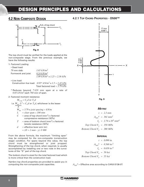
4.2.1 TOP CHORD PROPERTIES - D500 TM<br />
2 mm<br />
(0.08”)<br />
17 mm<br />
(0.68”)<br />
X X<br />
Fig. 9<br />
METRIC<br />
t = 2.3 mm<br />
Anet * = 361 mm2 Ix = 2.74 x 105 mm4 Top Chord Fy = 350 MPa<br />
Bottom Chord Fy = 380 MPa<br />
IMPERIAL<br />
t = 0.090 in.<br />
Anet * = 0.560 in. 2<br />
Ix = 0.658 in. 4<br />
Top Chord Fy = 50 ksi<br />
Bottom Chord Fy = 55 ksi<br />
A net *= Effective area according to CAN3-S136-01<br />
Y<br />
Y<br />
t