MEP-Technical Manual CDN 0408.qxd - Hambro
MEP-Technical Manual CDN 0408.qxd - Hambro
MEP-Technical Manual CDN 0408.qxd - Hambro

You also want an ePaper? Increase the reach of your titles
YUMPU automatically turns print PDFs into web optimized ePapers that Google loves.
DESIGN PRINCIPLES AND CALCULATIONS<br />
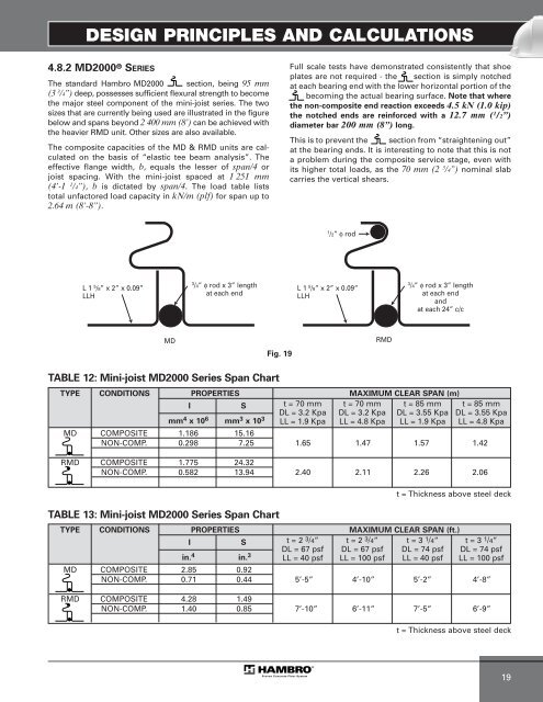
4.8.2 MD2000 ® SERIES<br />
The standard <strong>Hambro</strong> MD2000 section, being 95 mm<br />
(3 3 /4”) deep, possesses sufficient flexural strength to become<br />
the major steel component of the mini-joist series. The two<br />
sizes that are currently being used are illustrated in the figure<br />
below and spans beyond 2 400 mm (8’) can be achieved with<br />
the heavier RMD unit. Other sizes are also available.<br />
The composite capacities of the MD & RMD units are calculated<br />
on the basis of “elastic tee beam analysis”. The<br />
effective flange width, b, equals the lesser of span/4 or<br />
joist spacing. With the mini-joist spaced at 1 251 mm<br />
(4’-1 1 /4”), b is dictated by span/4. The load table lists<br />
total unfactored load capacity in kN/m (plf) for span up to<br />
2.64 m (8’-8”).<br />
L 1 5 /8” x 2” x 0.09”<br />
LLH<br />
MD<br />
3 /4” φ rod x 3” length<br />
at each end<br />
TABLE 12: Mini-joist MD2000 Series Span Chart<br />
TABLE 13: Mini-joist MD2000 Series Span Chart<br />
Fig. 19<br />
Full scale tests have demonstrated consistently that shoe<br />
plates are not required - the section is simply notched<br />
at each bearing end with the lower horizontal portion of the<br />
becoming the actual bearing surface. Note that where<br />
the non-composite end reaction exceeds 4.5 kN (1.0 kip)<br />
the notched ends are reinforced with a 12.7 mm ( 1 /2”)<br />
diameter bar 200 mm (8”) long.<br />
This is to prevent the section from “straightening out”<br />
at the bearing ends. It is interesting to note that this is not<br />
a problem during the composite service stage, even with<br />
its higher total loads, as the 70 mm (2 3 /4”) nominal slab<br />
carries the vertical shears.<br />
1 /2” φ rod<br />
L 1 5 /8” x 2” x 0.09”<br />
LLH<br />
RMD<br />
3 /4” φ rod x 3” length<br />
at each end<br />
and<br />
at each 24” c/c<br />
TYPE CONDITIONS PROPERTIES MAXIMUM CLEAR SPAN (m)<br />
I<br />
mm<br />
S<br />
4 x 106 mm3 x 103 t= 70mm<br />
DL = 3.2 Kpa<br />
LL = 1.9 Kpa<br />
t=70mm<br />
DL = 3.2 Kpa<br />
LL = 4.8 Kpa<br />
t=85mm<br />
DL = 3.55 Kpa<br />
LL = 1.9 Kpa<br />
t=85mm<br />
DL = 3.55 Kpa<br />
LL = 4.8 Kpa<br />
MD COMPOSITE 1.186 15.16<br />
NON-COMP. 0.298 7.25 1.65 1.47 1.57 1.42<br />
RMD COMPOSITE 1.775 24.32<br />
NON-COMP. 0.582 13.94 2.40 2.11 2.26 2.06<br />
t = Thickness above steel deck<br />
TYPE CONDITIONS PROPERTIES MAXIMUM CLEAR SPAN (ft.)<br />
I<br />
in.<br />
S<br />
4 in. 3<br />
t= 2<br />
MD COMPOSITE 2.85 0.92<br />
NON-COMP. 0.71 0.44 5’-5” 4’-10” 5’-2” 4’-8”<br />
3/4” t = 2 3/4” t = 3 1/4” t = 3 1/4”<br />
DL = 67 psf<br />
LL = 40 psf<br />
DL = 67 psf<br />
LL = 100 psf<br />
DL = 74 psf<br />
LL = 40 psf<br />
DL = 74 psf<br />
LL = 100 psf<br />
RMD COMPOSITE 4.28 1.49<br />
NON-COMP. 1.40 0.85 7’-10” 6’-11” 7’-5” 6’-9”<br />
t = Thickness above steel deck<br />
19