MEP-Technical Manual CDN 0408.qxd - Hambro
MEP-Technical Manual CDN 0408.qxd - Hambro
MEP-Technical Manual CDN 0408.qxd - Hambro

Create successful ePaper yourself
Turn your PDF publications into a flip-book with our unique Google optimized e-Paper software.
12<br />
DESIGN PRINCIPLES AND CALCULATIONS<br />
4.4 INTERFACE SHEAR<br />
The <strong>Hambro</strong> joist comprises a composite concrete slabsteel<br />
joist system with composite action achieved by the<br />
shear connection developed by two means:<br />
(i) by anchorage provided at the joist ends by<br />
means of a steel angle which acts both as a<br />
bearing shoe and as anchorage for the end<br />
diagonal, thereby producing horizontal bearing<br />
forces. This horizontal force is closely associated<br />
with the concrete strength and the vertical<br />
size of the steel angle plate on the shoe.<br />
(ii) by bond or friction between the partially<br />
embedded specially profiled top chord.<br />
Composite action between the section and the concrete<br />
slab exists because of the unique shear resistance developed<br />
along the interface between the two materials. This shear<br />
resistance, which has been called “bond” or “interface<br />
shear” is primarily the result of a “locking” or “clamping”<br />
action in the longitudinal direction between the concrete and<br />
the section when the composite joist is deflected under<br />
load. Another contributing factor to the shear resistance is<br />
the lateral compression stress or “poisson’s effect” which<br />
results from slab continuity in the lateral direction. This<br />
continuity prevents lateral expansion from occuring as a<br />
result of longitudinal compression stresses and thus lateral<br />
compression stress results. However, this effect has been<br />
ignored in determining interface shear capacity which has<br />
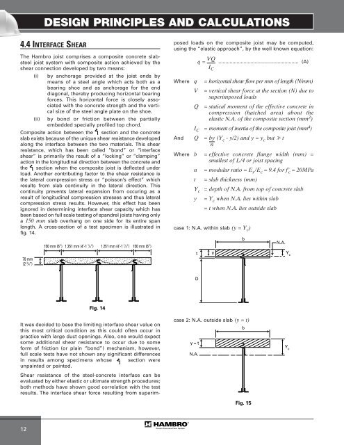
been based on full scale testing of spandrel joists having only<br />
a 150 mm slab overhang on one side for its entire span<br />
length. A cross-section of a test specimen is illustrated in<br />
fig. 14.<br />
70 mm<br />
(2 3 /4”)<br />
150 mm (6”) 1 251 mm (4’-1 150 mm (6”)<br />
1 /4”) 1 251 mm (4’-1 1 /4”)<br />
Fig. 14<br />
It was decided to base the limiting interface shear value on<br />
this most critical condition as this could often occur in<br />
practice with large duct openings. Also, one would expect<br />
some additional shear resistance to occur due to some<br />
form of friction (or plain “bond”) mechanism, however,<br />
full scale tests have not shown any significant differences<br />
in results among specimens whose section were<br />
unpainted or painted.<br />
Shear resistance of the steel-concrete interface can be<br />
evaluated by either elastic or ultimate strength procedures;<br />
both methods have shown good correlation with the test<br />
results. The interface shear force resulting from superim-<br />
posed loads on the composite joist may be computed,<br />
using the “elastic approach”, by the well known equation:<br />
......................................................... (A)<br />
Where q = horizontal shear flow per mm of length (N/mm)<br />
V = vertical shear force at the section (N) due to<br />
superimposed loads<br />
Q = statical moment of the effective concrete in<br />
compression (hatched area) about the<br />
elastic N.A. of the composite section (mm3 )<br />
IC = moment of inertia of the composite joist (mm4 )<br />
And Q = by (Yc - y/2) and y = yc but � t<br />
n<br />
Where b = effective concrete flange width (mm) =<br />
smallest of L/4 or joist spacing<br />
n = modular ratio = Es /Ec = 9.4 for f’ c = 20MPa<br />
t = slab thickness (mm)<br />
Yc = depth of N.A. from top of concrete slab<br />
y = Yc when N.A. lies within slab<br />
= t when N.A. lies outside slab<br />
case 1: N.A. within slab (y = Y c )<br />
t<br />
D<br />
y = t<br />
N.A.<br />
q = VQ<br />
I C<br />
case 2: N.A. outside slab (y = t)<br />
b<br />
y Y c<br />
b<br />
Fig. 15<br />
N.A.<br />
Y c