OS-C501
Create successful ePaper yourself
Turn your PDF publications into a flip-book with our unique Google optimized e-Paper software.
Offshore Standard DNV-<strong>OS</strong>-<strong>C501</strong>, November 2013<br />
Sec.6 Failure mechanisms and design criteria – Page 105<br />
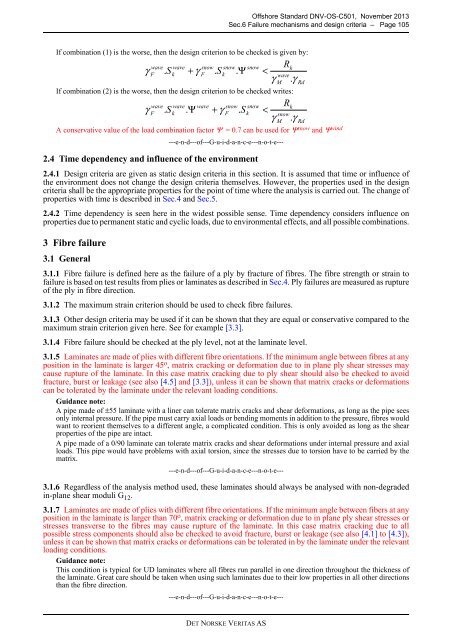
If combination (1) is the worse, then the design criterion to be checked is given by:<br />
If combination (2) is the worse, then the design criterion to be checked writes:<br />
A conservative value of the load combination factor Ψ = 0.7 can be used for Ψ snow and Ψ wind<br />
---e-n-d---of---G-u-i-d-a-n-c-e---n-o-t-e---<br />
2.4 Time dependency and influence of the environment<br />
2.4.1 Design criteria are given as static design criteria in this section. It is assumed that time or influence of<br />
the environment does not change the design criteria themselves. However, the properties used in the design<br />
criteria shall be the appropriate properties for the point of time where the analysis is carried out. The change of<br />
properties with time is described in Sec.4 and Sec.5.<br />
2.4.2 Time dependency is seen here in the widest possible sense. Time dependency considers influence on<br />
properties due to permanent static and cyclic loads, due to environmental effects, and all possible combinations.<br />
3 Fibre failure<br />
3.1 General<br />
γ<br />
γ<br />
wave wave snow snow snow<br />
F<br />
. Sk<br />
+ γ<br />
F<br />
. Sk<br />
. Ψ <<br />
S<br />
wave wave wave snow snow<br />
F<br />
.<br />
k<br />
. Ψ + γ<br />
F<br />
.<br />
k<br />
<<br />
3.1.1 Fibre failure is defined here as the failure of a ply by fracture of fibres. The fibre strength or strain to<br />
failure is based on test results from plies or laminates as described in Sec.4. Ply failures are measured as rupture<br />
of the ply in fibre direction.<br />
3.1.2 The maximum strain criterion should be used to check fibre failures.<br />
3.1.3 Other design criteria may be used if it can be shown that they are equal or conservative compared to the<br />
maximum strain criterion given here. See for example [3.3].<br />
3.1.4 Fibre failure should be checked at the ply level, not at the laminate level.<br />
3.1.5 Laminates are made of plies with different fibre orientations. If the minimum angle between fibres at any<br />
position in the laminate is larger 45 o , matrix cracking or deformation due to in plane ply shear stresses may<br />
cause rupture of the laminate. In this case matrix cracking due to ply shear should also be checked to avoid<br />
fracture, burst or leakage (see also [4.5] and [3.3]), unless it can be shown that matrix cracks or deformations<br />
can be tolerated by the laminate under the relevant loading conditions.<br />
Guidance note:<br />
A pipe made of ±55 laminate with a liner can tolerate matrix cracks and shear deformations, as long as the pipe sees<br />
only internal pressure. If the pipe must carry axial loads or bending moments in addition to the pressure, fibres would<br />
want to reorient themselves to a different angle, a complicated condition. This is only avoided as long as the shear<br />
properties of the pipe are intact.<br />
A pipe made of a 0/90 laminate can tolerate matrix cracks and shear deformations under internal pressure and axial<br />
loads. This pipe would have problems with axial torsion, since the stresses due to torsion have to be carried by the<br />
matrix.<br />
---e-n-d---of---G-u-i-d-a-n-c-e---n-o-t-e---<br />
3.1.6 Regardless of the analysis method used, these laminates should always be analysed with non-degraded<br />
in-plane shear moduli G 12 .<br />
3.1.7 Laminates are made of plies with different fibre orientations. If the minimum angle between fibers at any<br />
position in the laminate is larger than 70 o , matrix cracking or deformation due to in plane ply shear stresses or<br />
stresses transverse to the fibres may cause rupture of the laminate. In this case matrix cracking due to all<br />
possible stress components should also be checked to avoid fracture, burst or leakage (see also [4.1] to [4.3]),<br />
unless it can be shown that matrix cracks or deformations can be tolerated in by the laminate under the relevant<br />
loading conditions.<br />
Guidance note:<br />
This condition is typical for UD laminates where all fibres run parallel in one direction throughout the thickness of<br />
the laminate. Great care should be taken when using such laminates due to their low properties in all other directions<br />
than the fibre direction.<br />
---e-n-d---of---G-u-i-d-a-n-c-e---n-o-t-e---<br />
S<br />
γ<br />
γ<br />
R<br />
k<br />
wave<br />
M<br />
.<br />
R<br />
γ<br />
k<br />
snow<br />
M<br />
.<br />
γ<br />
Rd<br />
Rd<br />
DET NORSKE VERITAS AS


