

OS-C501

You also want an ePaper? Increase the reach of your titles
YUMPU automatically turns print PDFs into web optimized ePapers that Google loves.
Offshore Standard DNV-<strong>OS</strong>-<strong>C501</strong>, November 2013<br />
Sec.4 Materials - laminates – Page 73<br />
Table 4-16 Default changes of ply properties with matrix damage<br />
Matrix cracking due to stress<br />
(see failure criteria in Sec.6 [4])<br />
Change ply properties to<br />
(see also [9.2.3])<br />
stress σ 2 transverse to the fibre direction E 2 = ν 12 = 0<br />
shear stress σ 12 G 12 = ν 12 = 0<br />
stress σ 3 transverse to the fibre direction E 3 = ν 31 = 0<br />
shear stress σ 13 G 13 = ν 13 = 0<br />
shear stress σ 23 G 23 = ν 23 = 0<br />
9.2.3 In numerical calculations certain problems may arise, e.g. lack of ability to invert the structural stiffness<br />
matrix, when degraded material properties are set equal to 0. To overcome such problems, one may apply small<br />
values, e.g. 1% of the non-degraded values, instead of 0.<br />
Guidance note:<br />
Stiffness of a composite in compression will be similar to the linear (initial) value even under the presence of damage,<br />
since matrix cracks will close. In tension, the stiffness reduces gradually with the increase of damage.<br />
9.3 Experimental approach<br />
---e-n-d---of---G-u-i-d-a-n-c-e---n-o-t-e---<br />
9.3.1 Instead of the default values given in [9.2], gradual degradation of the material properties at ply levels<br />
can be used, provided experiments document the validity of values larger than 0 for the type of laminate used.<br />
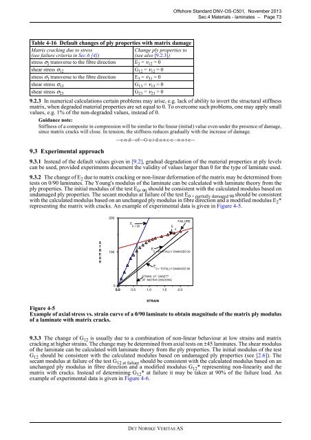
9.3.2 The change of E 2 due to matrix cracking or non-linear deformation of the matrix may be determined from<br />
tests on 0/90 laminates. The Young's modulus of the laminate can be calculated with laminate theory from the<br />
ply properties. The initial modulus of the test E 0+90 should be consistent with the calculated modulus based on<br />
undamaged ply properties. The secant modulus at failure of the test E 0 + partially damaged 90 should be consistent<br />
with the calculated modulus based on an unchanged ply modulus in fibre direction and a modified modulus E 2 *<br />
representing the matrix with cracks. An example of experimental data is given in Figure 4-5.<br />
.<br />
200<br />
E<br />
II<br />
FAILURE<br />
E<br />
0 + 90<br />
E 0 + PARTIALLY DAMAGED 90<br />
S<br />
T<br />
R<br />
E<br />
S<br />
S<br />
100<br />
E 0 + TOTALLY DAMAGED 90<br />
STRAIN AT ONSETT<br />
OF MATRIX CRACKING<br />
0<br />
0.0<br />
0.5<br />
1.0<br />
1.5<br />
2.0<br />
STRAIN<br />
Figure 4-5<br />
Example of axial stress vs. strain curve of a 0/90 laminate to obtain magnitude of the matrix ply modulus<br />
of a laminate with matrix cracks.<br />
9.3.3 The change of G 12 is usually due to a combination of non-linear behaviour at low strains and matrix<br />
cracking at higher strains. The change may be determined from axial tests on ±45 laminates. The shear modulus<br />
of the laminate can be calculated with laminate theory from the ply properties. The initial modulus of the test<br />
G 12 should be consistent with the calculated modulus based on undamaged ply properties (see [2.6]). The<br />
secant modulus at failure of the test G 12 at failure should be consistent with the calculated modulus based on an<br />
unchanged ply modulus in fibre direction and a modified modulus G 12 * representing non-linearity and the<br />
matrix with cracks. Instead of determining G 12 * at failure it may be taken at 90% of the failure load. An<br />
example of experimental data is given in Figure 4-6.<br />
DET NORSKE VERITAS AS