

OS-C501

You also want an ePaper? Increase the reach of your titles
YUMPU automatically turns print PDFs into web optimized ePapers that Google loves.
Offshore Standard DNV-<strong>OS</strong>-<strong>C501</strong>, November 2013<br />
Sec.9 Structural analysis – Page 143<br />
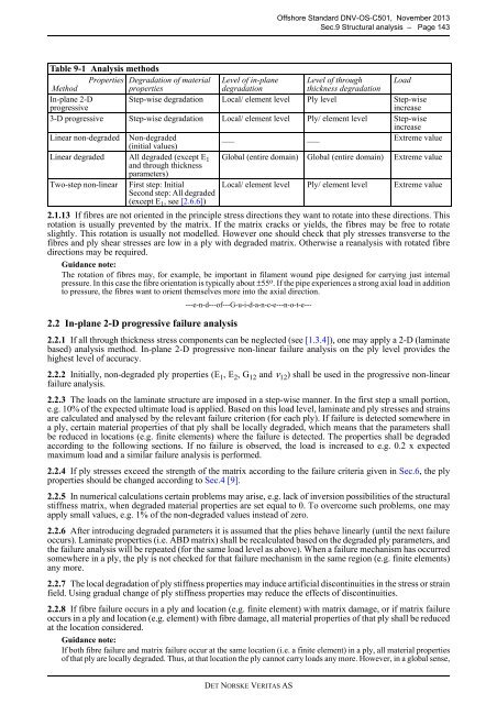
Table 9-1 Analysis methods<br />
Properties Degradation of material Level of in-plane Level of through Load<br />
Method<br />
properties<br />
degradation<br />
thickness degradation<br />
In-plane 2-D<br />
progressive<br />
Step-wise degradation Local/ element level Ply level Step-wise<br />
increase<br />
3-D progressive Step-wise degradation Local/ element level Ply/ element level Step-wise<br />
increase<br />
Linear non-degraded Non-degraded<br />
___ ___ Extreme value<br />
(initial values)<br />
Linear degraded All degraded (except E 1<br />
and through thickness<br />
Global (entire domain) Global (entire domain) Extreme value<br />
parameters)<br />
Two-step non-linear First step: Initial<br />
Second step: All degraded<br />
(except E 1 , see [2.6.6])<br />
Local/ element level Ply/ element level Extreme value<br />
2.1.13 If fibres are not oriented in the principle stress directions they want to rotate into these directions. This<br />
rotation is usually prevented by the matrix. If the matrix cracks or yields, the fibres may be free to rotate<br />
slightly. This rotation is usually not modelled. However one should check that ply stresses transverse to the<br />
fibres and ply shear stresses are low in a ply with degraded matrix. Otherwise a reanalysis with rotated fibre<br />
directions may be required.<br />
Guidance note:<br />
The rotation of fibres may, for example, be important in filament wound pipe designed for carrying just internal<br />
pressure. In this case the fibre orientation is typically about ±55 o . If the pipe experiences a strong axial load in addition<br />
to pressure, the fibres want to orient themselves more into the axial direction.<br />
2.2 In-plane 2-D progressive failure analysis<br />
---e-n-d---of---G-u-i-d-a-n-c-e---n-o-t-e---<br />
2.2.1 If all through thickness stress components can be neglected (see [1.3.4]), one may apply a 2-D (laminate<br />
based) analysis method. In-plane 2-D progressive non-linear failure analysis on the ply level provides the<br />
highest level of accuracy.<br />
2.2.2 Initially, non-degraded ply properties (E 1 , E 2 , G 12 and ν 12 ) shall be used in the progressive non-linear<br />
failure analysis.<br />
2.2.3 The loads on the laminate structure are imposed in a step-wise manner. In the first step a small portion,<br />
e.g. 10% of the expected ultimate load is applied. Based on this load level, laminate and ply stresses and strains<br />
are calculated and analysed by the relevant failure criterion (for each ply). If failure is detected somewhere in<br />
a ply, certain material properties of that ply shall be locally degraded, which means that the parameters shall<br />
be reduced in locations (e.g. finite elements) where the failure is detected. The properties shall be degraded<br />
according to the following sections. If no failure is observed, the load is increased to e.g. 0.2 x expected<br />
maximum load and a similar failure analysis is performed.<br />
2.2.4 If ply stresses exceed the strength of the matrix according to the failure criteria given in Sec.6, the ply<br />
properties should be changed according to Sec.4 [9].<br />
2.2.5 In numerical calculations certain problems may arise, e.g. lack of inversion possibilities of the structural<br />
stiffness matrix, when degraded material properties are set equal to 0. To overcome such problems, one may<br />
apply small values, e.g. 1% of the non-degraded values instead of zero.<br />
2.2.6 After introducing degraded parameters it is assumed that the plies behave linearly (until the next failure<br />
occurs). Laminate properties (i.e. ABD matrix) shall be recalculated based on the degraded ply parameters, and<br />
the failure analysis will be repeated (for the same load level as above). When a failure mechanism has occurred<br />
somewhere in a ply, the ply is not checked for that failure mechanism in the same region (e.g. finite elements)<br />
any more.<br />
2.2.7 The local degradation of ply stiffness properties may induce artificial discontinuities in the stress or strain<br />
field. Using gradual change of ply stiffness properties may reduce the effects of discontinuities.<br />
2.2.8 If fibre failure occurs in a ply and location (e.g. finite element) with matrix damage, or if matrix failure<br />
occurs in a ply and location (e.g. element) with fibre damage, all material properties of that ply shall be reduced<br />
at the location considered.<br />
Guidance note:<br />
If both fibre failure and matrix failure occur at the same location (i.e. a finite element) in a ply, all material properties<br />
of that ply are locally degraded. Thus, at that location the ply cannot carry loads any more. However, in a global sense,<br />
DET NORSKE VERITAS AS