OS-C501
Create successful ePaper yourself
Turn your PDF publications into a flip-book with our unique Google optimized e-Paper software.
Offshore Standard DNV-<strong>OS</strong>-<strong>C501</strong>, November 2013<br />
Sec.6 Failure mechanisms and design criteria – Page 120<br />
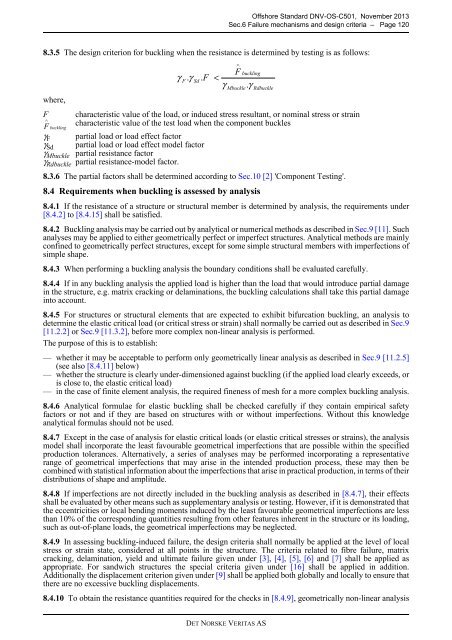
8.3.5 The design criterion for buckling when the resistance is determined by testing is as follows:<br />
where,<br />
F<br />
F ∧<br />
buckling<br />
γ F<br />
γ Sd<br />
γ Mbuckle<br />
γ . γ . F <<br />
characteristic value of the load, or induced stress resultant, or nominal stress or strain<br />
characteristic value of the test load when the component buckles<br />
partial load or load effect factor<br />
partial load or load effect model factor<br />
partial resistance factor<br />
γ Rdbuckle partial resistance-model factor.<br />
8.3.6 The partial factors shall be determined according to Sec.10 [2] 'Component Testing'.<br />
8.4 Requirements when buckling is assessed by analysis<br />
F<br />
Sd<br />
Rdbuckle<br />
8.4.1 If the resistance of a structure or structural member is determined by analysis, the requirements under<br />
[8.4.2] to [8.4.15] shall be satisfied.<br />
8.4.2 Buckling analysis may be carried out by analytical or numerical methods as described in Sec.9 [11]. Such<br />
analyses may be applied to either geometrically perfect or imperfect structures. Analytical methods are mainly<br />
confined to geometrically perfect structures, except for some simple structural members with imperfections of<br />
simple shape.<br />
8.4.3 When performing a buckling analysis the boundary conditions shall be evaluated carefully.<br />
γ<br />
8.4.4 If in any buckling analysis the applied load is higher than the load that would introduce partial damage<br />
in the structure, e.g. matrix cracking or delaminations, the buckling calculations shall take this partial damage<br />
into account.<br />
8.4.5 For structures or structural elements that are expected to exhibit bifurcation buckling, an analysis to<br />
determine the elastic critical load (or critical stress or strain) shall normally be carried out as described in Sec.9<br />
[11.2.2] or Sec.9 [11.3.2], before more complex non-linear analysis is performed.<br />
The purpose of this is to establish:<br />
— whether it may be acceptable to perform only geometrically linear analysis as described in Sec.9 [11.2.5]<br />
(see also [8.4.11] below)<br />
— whether the structure is clearly under-dimensioned against buckling (if the applied load clearly exceeds, or<br />
is close to, the elastic critical load)<br />
— in the case of finite element analysis, the required fineness of mesh for a more complex buckling analysis.<br />
8.4.6 Analytical formulae for elastic buckling shall be checked carefully if they contain empirical safety<br />
factors or not and if they are based on structures with or without imperfections. Without this knowledge<br />
analytical formulas should not be used.<br />
8.4.7 Except in the case of analysis for elastic critical loads (or elastic critical stresses or strains), the analysis<br />
model shall incorporate the least favourable geometrical imperfections that are possible within the specified<br />
production tolerances. Alternatively, a series of analyses may be performed incorporating a representative<br />
range of geometrical imperfections that may arise in the intended production process, these may then be<br />
combined with statistical information about the imperfections that arise in practical production, in terms of their<br />
distributions of shape and amplitude.<br />
8.4.8 If imperfections are not directly included in the buckling analysis as described in [8.4.7], their effects<br />
shall be evaluated by other means such as supplementary analysis or testing. However, if it is demonstrated that<br />
the eccentricities or local bending moments induced by the least favourable geometrical imperfections are less<br />
than 10% of the corresponding quantities resulting from other features inherent in the structure or its loading,<br />
such as out-of-plane loads, the geometrical imperfections may be neglected.<br />
8.4.9 In assessing buckling-induced failure, the design criteria shall normally be applied at the level of local<br />
stress or strain state, considered at all points in the structure. The criteria related to fibre failure, matrix<br />
cracking, delamination, yield and ultimate failure given under [3], [4], [5], [6] and [7] shall be applied as<br />
appropriate. For sandwich structures the special criteria given under [16] shall be applied in addition.<br />
Additionally the displacement criterion given under [9] shall be applied both globally and locally to ensure that<br />
there are no excessive buckling displacements.<br />
Mbuckle<br />
buckling<br />
8.4.10 To obtain the resistance quantities required for the checks in [8.4.9], geometrically non-linear analysis<br />
∧<br />
F<br />
. γ<br />
DET NORSKE VERITAS AS


