

OS-C501

Create successful ePaper yourself
Turn your PDF publications into a flip-book with our unique Google optimized e-Paper software.
Offshore Standard DNV-<strong>OS</strong>-<strong>C501</strong>, November 2013<br />
Sec.6 Failure mechanisms and design criteria – Page 123<br />
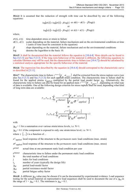
10.4.4 It is assumed that the reduction of strength with time can be described by one of the following<br />
equations:<br />
where,<br />
− β log t<br />
or<br />
or σ(t) = σ(1) – β log(t)<br />
or ε(t) = ε(1) – β log(t)<br />
σ (t), ε (t) time-dependent stress or strain to failure<br />
σ(1) , ε(1) scalar depending on the material, failure mechanism and on the environmental conditions at time<br />
1 (units of time must be consistent in the equation)<br />
β slope depending on the material, failure mechanism and on the environmental conditions<br />
log denotes the logarithm to the basis 10.<br />
10.4.5 It shall be documented that the material follows the equation in [10.4.4]. More details can be found in<br />
Sec.4 [3.3] and Sec.5 [3.3]. If the long term behaviour of the material is different, the following equations to<br />
calculate lifetimes may still be used, but the characteristic time to failure (see [10.4.7]) should be calculated by<br />
a statistical analysis appropriate for the specific behaviour of the material.<br />
10.4.6 The regression line described by the equation in [10.4.4] should correspond to the characteristic curve<br />
as described in [3.11].<br />
charact<br />
10.4.7 The characteristic time to failure t γ ⋅σ<br />
shall be extracted from the stress rupture curve (see<br />
Sd<br />
applied<br />
also Sec.4 [3.3] and Sec.5 [3.3]) for each applied strain condition. The characteristic time to failure shall be<br />
found for the applied strains ε applied multiplied by the partial load model factor γ Sd . Alternatively, the<br />
charact<br />
characteristic time to failure can also be found for an applied stain t ( γ ⋅ε<br />
) , depending on what type<br />
Sd<br />
applied<br />
of data is available. One of the following design criterion for stress rupture shall be used, depending what kind<br />
of long term data are available:<br />
with<br />
γ Rd = 1 for a summation over various strain/stress levels, i.e. N>1.<br />
γ Rd = 0.1 if the component is exposed to only one strain/stress level, i.e. N=1.<br />
where t<br />
ε j applied<br />
σ j applied<br />
t actual<br />
t charact<br />
N<br />
j<br />
t y<br />
γ Sd<br />
γ Rd<br />
γ fat<br />
{....}<br />
γ<br />
log<br />
log<br />
fat<br />
t is a function of…<br />
[ σ ( t)<br />
] = log[ σ ( 1)<br />
] ( )<br />
[ ε( t)<br />
] = log[ ε ( 1)<br />
] − β log( t)<br />
γ<br />
γ<br />
Rd<br />
fat<br />
t<br />
γ<br />
y<br />
Rd<br />
∑<br />
j = 1<br />
t<br />
( )<br />
{ σ applied }<br />
j<br />
Sd<br />
<<br />
{ } 1<br />
γ σ<br />
j applied<br />
local response of the structure to the permanent static load conditions (max. strain)<br />
local response of the structure to the permanent static load conditions (max. stress)<br />
actual time at one permanent static load condition per year<br />
N<br />
N<br />
t y∑<br />
j=<br />
1<br />
t<br />
charact<br />
actual<br />
characteristic time to failure under the permanent static load condition<br />
the total number of load conditions<br />
index for load conditions<br />
number of years (typically the design life)<br />
partial load-model factor<br />
partial resistance-model factor<br />
partial fatigue safety factor<br />
t<br />
t<br />
or<br />
actual<br />
charact<br />
10.4.8 A different γ Rd value may be chosen if it can be documented by experimental evidence. Load sequence<br />
testing for the actual material on representative load sequences shall be used to document the use of a γ Rd in<br />
the range of 1 > γ Rd > 0.1. The minimum is γ Rd = 0.1.<br />
γ<br />
Sd<br />
{ applied }<br />
j<br />
γ ε<br />
Sd<br />
<<br />
{ } 1<br />
γ ε<br />
j applied<br />
Sd<br />
DET NORSKE VERITAS AS