![BBBBflt] «BlJIUrIrlr - Clpdigital.org](https://img.yumpu.com/7384070/112/500x640/bbbbflt-bljiurirlr-clpdigitalorg.jpg)
BBBBflt] «BlJIUrIrlr - Clpdigital.org
BBBBflt] «BlJIUrIrlr - Clpdigital.org
BBBBflt] «BlJIUrIrlr - Clpdigital.org

You also want an ePaper? Increase the reach of your titles
YUMPU automatically turns print PDFs into web optimized ePapers that Google loves.
llll Foiling Stamping- HeatTieating<br />
acids started. Deep etching was accomplished by<br />
heating a piece of steel of definite size for a given time.<br />
in a solution of concentrated hydrochloric acid.<br />
It was found that by duplicating deep acid-etching<br />
conditions as nearly as possible in each text, we were<br />
able to make excellent comparisons between samples.<br />
In these etching tests it was noted that steels of different<br />
analyses varied in solubility and that the rate<br />
of solubility varied according to the amount of mechanical<br />
work which had been done upon the piece.<br />
Different annealing temperatures on the same steel<br />
caused differences in solubility. It was noted that<br />
steels made by the acid open hearth, basic open hearth<br />
or electric furnace methods could be distinguished one<br />
from the other, due to differences of solubility of steels<br />
of similar analysis. It was with great ease that samples<br />
taken from f<strong>org</strong>ings made from sand-cast and<br />
chill-cast ingots could be distinguished. These points<br />
are brought out simply to show the wide range and<br />
the possibilities of comparison of similar samples subjected<br />
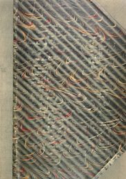
to the deep acid etch. Figs. 5, 6, 8 and 9 show<br />
the results of some deep etching tests made on bars<br />
cored from f<strong>org</strong>ings. Fig. 5 shows a bad surface condition<br />
with considerable pitting following the acid<br />
etch. The physical test properties of this specimen<br />
is shown in Table 1, text 1064. The elastic limit,<br />
elongation and reduction of area are below the specifications.<br />
Photomicrographs of this specimen are<br />
shown in Figs. 3 and 4. It will be noted that these<br />
three different methods of test lead to the<br />
same verdict, that is, that the steel was<br />
dirty and contained many sonims.<br />
Fig. 6 shows a specimen with less pronounced<br />
pits than those of Fig. 5. In order<br />
to establish whether or not these pits were<br />
in the center of the specimen, as well as on<br />
the surface, the same specimen was cut<br />
transversely and longitudinally and then<br />
deeply etched. After etching, the specimens<br />
were closely examined and it was found that<br />
where a fissure or pit existed on one segment<br />
there was a corresponding pit on the<br />
matching segment. Pitting occurred on interior<br />
sections as well as on the surface.<br />
Fig. 7 shows a bar of rolled wrought iron<br />
after it has been deeply etched. The rough<br />
fluted condition of the surface is due to the<br />
fact that the slag lines or inclusions in the<br />
bar have been eaten away by the acid, thus<br />
revealing the piling.<br />
Fig. 8 shows a sound bar of steel after<br />
it has been deeply etched. With the .exception<br />
of the fissure at the extreme upper end<br />
of the bar. this specimen shows no pitting or<br />
fissures. The crack at the top of the bar<br />
was produced by mechanically breaking the<br />
specimen, which upon deeply etching was<br />
enlarged to a fissure. Such hair line cracks<br />
which open up as fissures during deep acid-<br />
etching may be produced by extreme internal<br />
stress, or by impact. It has always been<br />
found that these fissures occur at right<br />
angles to the line of stress in the material<br />
and are apparently always intercrystalline as<br />
compared with intracrystalline cracks which<br />
are inherent in the material due to conditions<br />
of manufacture.<br />
March, 1925<br />
Some time subsequent to making these tests we<br />
were having difficulty in hardening certain areas of a<br />
gas engine cam shaft. These soft areas always appeared<br />
in the same location on the shaft regardless of<br />
the method or condition of heat treatment. Deep<br />
etching of numerous specimens cut from different<br />
cam shafts revealed the conditions as shown in Fig.<br />
10. The parting line of the f<strong>org</strong>ing die was at the<br />
part of this cam which was giving difficulty in hardening.<br />
In the f<strong>org</strong>ing of a cam shaft, clue to the nature<br />
of^its shape, the material flows in a horizontal direction<br />
until it meets the closed faces of the die, or until<br />
the flash chills. The material then flows perpendicularly<br />
upward and downward to fill the die. If ample<br />
curvature is not provided, or the dies are not brought<br />
down with the minimum thickness of flash, a number<br />
of fiber-like ends of worked-material are left on the<br />
f<strong>org</strong>ing at the parting of the dies. The mechanical<br />
working of steel between dies tends to move nonmetallic<br />
particles toward the parting line of the die,<br />
resulting in a concentration of these inclusions at the<br />
point where the best metal is wanted. Further examination<br />
of these specimens showed that it was evident<br />
that the trimmer die was not functioning properly<br />
and was tearing the metal in shearing, resulting in<br />
voids or fissures at the parting line of the dies. To<br />
properlv carburize and harden such material is of<br />
course quite impossible.<br />
FIG. 5—Photograph of a deeply etched bar showing many deep pits on the<br />
surface. FIG. 6—Photograph of a deeply etched bar showing fewer<br />
surface pits and cracks. Fig. 7—Photograph of a deeply etched rolled<br />
wrought iron bar showing a very rough surface resulting from the<br />
etching away of the elongated slag inclusions. FIG. 8—Photograph of a<br />
deeply etched sound bar showing an absence of pits and cracks with<br />
the exception of a minor fissure at the top of the bar which was caused<br />
by mechanically breaking the bar. FIG. 9—Photograph of a deeply<br />
etched bar showing very deep surface pits; photomicrograph of this<br />
bar is shown in Fig. 3.