Template BA B168xH238 - Hörmann
Template BA B168xH238 - Hörmann
Template BA B168xH238 - Hörmann
You also want an ePaper? Increase the reach of your titles
YUMPU automatically turns print PDFs into web optimized ePapers that Google loves.
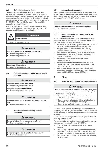
ENGLISH2.5 Safety instructions for fittingThe specialist carrying out the work must ensure thatinstallation is conducted in compliance with the prevailingnational job safety rules and regulations and those governingthe operation of electrical equipment. The relevant nationaldirectives must be observed. Potential hazards as outlined inDIN EN 13241-1 are avoided by construction and fittingaccording to our guidelines.After fitting has been completed, the installer of the gatesystem must declare conformity with DIN EN 13241-1 inaccordance with the scope of application.Mains voltage▶ See warning in section 3.4DangerWARNINGDanger of injury due to unwanted gate travel▶ See warning in section 3.2▶ See warning in section 3.8WARNINGUnsuitable fixing material▶ See warning in section 3.2.32.6Safety instructions for initial start-up and foroperationWARNINGDanger of injury during gate travel▶ See warning in sections 4 and 8Danger of crushing and shearing▶ See warning in sections 4 and 8CAUTIONDanger of injury due to the force value being set toohigh▶ See warning in section 4.3.12.7Safety instructions for using the handtransmitterWarningDanger of injury due to unwanted gate travel▶ See warning in section 6.1CautionDanger of injuries due to unintended gate travel▶ See warning in section 62.8 Approved safety equipmentSafety relevant functions or components of the control, suchas the force limit, external photocells and closing edge safetydevice, have been designed and approved in accordance withcategory 2, PL "c" of EN ISO 13849-1:2008.WARNINGDanger of injuries due to faulty safety equipment▶ See warning in section 4.62.8.1Safety information on compliance with theoperating forcesIf you observe these instructions, as well as the followingconditions, you can assume that the operating forces arecomplied with according to DIN EN 12453:• The centre of gravity for the gate must be in the centre ofthe gate (maximum permissible deviation ± 20%).• The gate is easy to move and does not have anygradients/slopes (0%).• A Hörmann sound-absorbing seal DP 3 is fitted to theclosing edge(s). This must be ordered separately(article no.: 436 388).• The operator is programmed for slow speed(see section 4.3.2).• The reversal limit at 50 mm opening width has beenchecked and maintained over the entire length of themain closing edge.• The distance between the supporting rollers in selfsupportinggates (maximum width 6200 mm, maximumopening width 4000 mm) is max. 2000 mm.3Fitting3.1 Inspecting and preparing the gate/gate systemWARNINGDanger of injury due to a malfunction in the gate systemA malfunction in the gate system or an incorrectly alignedgate can cause serious injury▶ Do not use the gate system if repair or adjustmentwork must be conducted.▶ Check the entire gate system (joints, gate bearings andfastenings) for wear and possible damage.▶ Check for signs of rust, corrosion or fractures.The sliding gate operator is not designed for operation withsluggish gates, that is, gates that can no longer be opened orclosed manually, or can only be opened/closed manually withdifficulty.The operator is only designed for use with gates that do nothave any gradient or slope.The gate must be in a flawless mechanical condition, so thatit can be easily operated by hand (EN 12604).▶ Check whether the gate can be opened and closedcorrectly.▶ Immobilize any mechanical locks not needed for poweroperation of the sliding gate. This includes in particularany locking mechanisms connected with the gate lock.▶ Mechanically secure the gate to prevent it from runningout of its guides.28 TR10A082-C RE / 01.2011


