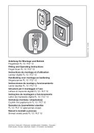
Template BA B168xH238 - Hörmann
Template BA B168xH238 - Hörmann
Template BA B168xH238 - Hörmann

Create successful ePaper yourself
Turn your PDF publications into a flip-book with our unique Google optimized e-Paper software.
ENGLISH4.5 Reversal limitDuring operation of the gate in the CLOSE direction, thesystem must distinguish between two possibilities: whetherthe gate contacts the end stop (gate system stops) or anobstruction (gate reverses direction). The limit range can beadjusted as follows (see Figure 9.4).Setting the reversal limit:1. Set DIL switch 11 to ON.The reversal limit can now be set step-by-step.2. Briefly press print button P to decrease the reversal limit.Briefly press print button T to increase the reversal limit.During adjustment, the green LED will indicate thefollowing settings:1x flashingup to10x flashingMinimum reversal limit, the green LEDflashes onceMaximum reversal limit, the green LEDflashes 10 times3. Set DIL switch 11 back to OFF to store the set reversallimit.4.6 Automatic timed closingNOTE:Automatic timed closing can only be activated if at least onesafety device has been connected. This is required accordingto DIN EN 13241-1.The hold-open phase can be set for operation with automatictimed closing (see Figure 9.5).Setting the hold-open phase:1. Set DIL switch 13 to ON.The hold-open phase can now be set in increments.2. Briefly press print button P to decrease the hold-openphase.Briefly press print button P to increase the hold-openphase.During adjustment, the green LED will indicate thefollowing settings:1x flashing2x flashing3x flashing4x flashing5x flashing30 second hold-open phase60 second hold-open phase90 second hold-open phase120 second hold-open phase180 second hold-open phase3. Set DIL switch 13 back to OFF to store the set holdopenphase.WARNINGDanger of injuries due to faulty safety equipmentIn the event of a malfunction, there is a danger of injuriesdue to faulty safety equipment.▶ After the learning runs, the person commissioning thesystem must check the function(s) of the safetyequipment.The system is ready for operation only after this.5 DIL Switch FunctionsThe control is programmed via the DIL switches. Before initialstart-up, the DIL switches are in the factory settings, i.e. allthe switches are in the OFF position. Changes to the DILswitch settings are only permissible under the followingconditions:• The operator is at rest.• The warning or hold-open phase is not active.The DIL switches must be set as described below inaccordance with the national regulations, the desired safetyequipment and the on-site circumstances.5.1DIL switch 1Installation direction:▶ See Figure 7.11 ON Gate closes to the right (as viewed from theoperator)1 OFF Gate closes to the left (as viewed from theoperator)5.2DIL switch 2Set-up mode:▶ See Figures 8.1a – cThe safety and protective devices are not active during set-upmode.2 ON • Teach-in gate travel• Delete gate data2 OFF Normal mode5.3 DIL switch 3/DIL switch 4SE1 safety device (opening):▶ See Figure 9.6The functions of the SE1 are set with DIL switch 3 incombination with DIL switch 4.3 ON Activation kit for closing edge safety device orphotocell with testing3 OFF • 8k2 resistance contact strip• Photocell from another manufacturer• No safety device (8k2 resistance betweenterminals 20/72, delivery status)4 ON Brief, immediate reversing in the CLOSE direction(for SKS)4 OFF Brief, delayed reversing in the CLOSE direction(for photocell)34 TR10A082-C RE / 01.2011