Erfolgreiche ePaper selbst erstellen
Machen Sie aus Ihren PDF Publikationen ein blätterbares Flipbook mit unserer einzigartigen Google optimierten e-Paper Software.
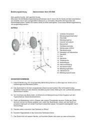
• Connect the pairs of pushrods 4.11 and 5.12, and 4.12 and 5.13, using the collets 5.15 and grubscrews<br />
5.16.<br />
• Hold the horns against the control surfaces. The pushrods should run as straight as possible, and<br />
not be under tension. If necessary, file out the slots in part 5.3 until this is so.<br />
• Make sure that the horns are positioned far enough outboard on the control surfaces to eliminate<br />
any danger of them fouling the propeller.<br />
• Loosen the grubscrews 5.16. With the control surfaces at neutral, glue the horns to them with instant<br />
glue. Caution: the holes in the horns and the pushrods must be located exactly at right-angles<br />
to the pivot axis of the hinges - note the dotted line in the plan view and the side view.<br />
• Bend one end of the switch pushrod 5.17 as shown on the plan, and install the third guide tube 5.14.<br />
• Slip the pushrod 5.17 through the bottom slot, and connect it to the pushrod 4.3 by means of the<br />
collet 5.18 and the grubscrew 5.19.<br />
• Glue the guide tubes to the rear <strong>hu</strong>ll section.<br />
Checking the working systems<br />
At this stage you should check that the various systems work correctly. First switch the transmitter on.<br />
The motor controller stick must be at the „Motor off“ position.<br />
• Pull the pushrod 5.17 back to switch the radio control system on.<br />
48<br />
Caution:<br />
As the main battery 4.2 supplies power to the radio control system as well as the main<br />
motor, the motor will run briefly when you switch on. Keep your fingers well away from the<br />
propeller, to avoid injury.<br />
• The control surfaces should be exactly at centre when the servos are at „neutral“ (sticks and trims<br />
central).<br />
• If you need to adjust the linkages, undo the corresponding grub screw 5.16. Slide the pushrods to<br />
the correct position, then tighten the screw again.<br />
• Check the control surface deflections and the direction of servo rotation. If any control system works<br />
in the wrong „sense“, reverse the servo inside your transmitter.<br />
• Check the direction of motor rotation once more. The propeller must rotate to the left (anti-clockwise)<br />
for forwards running, when viewed from the rear.