Sie wollen auch ein ePaper? Erhöhen Sie die Reichweite Ihrer Titel.
YUMPU macht aus Druck-PDFs automatisch weboptimierte ePaper, die Google liebt.
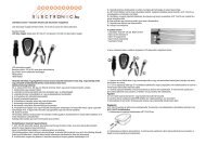
• Glue the stern tube support 2.10 on the plates 2.9.<br />
• Glue the mounting plates 2.11 in place, butting up against parts 2.9 / 2.10.<br />
• Place the motor / gearbox assembly in the aperture in the insert plate from underneath. Sand back<br />
the mounting plates 2.11 if necessary.<br />
• Drill 1.5 mm holes through the horizontal webs of the gearbox housing and the plates 2.11, to take<br />
the self-tapping screws 2.13.<br />
• Remove the motor assembly and drill out the holes in the gearbox housing to 2.5 mm diameter.<br />
• Install the motor assembly, fixing it in place with the washers 2.12 and the self-tapping screws 2.13.<br />
• Push up the rear buoyancy <strong>hu</strong>ll cap 1.8 against the insert plate, but do not glue it yet. The insert plate<br />
must fit into the inside slots in the buoyancy <strong>hu</strong>ll cap.<br />
• Cut and file out the rectangular aperture and screw holes in the switch bulkhead 2.14 for the radio<br />
system switch. Trim the switch bulkhead to fit, and glue it to the stern tube support 2.10 only, using<br />
instant glue.<br />
• Cut a rectangular slot, about 3 mm wide and 5 mm long, in the front end of the depth vane guide<br />
tube 2.15 - detail drawing „Z“.<br />
• Cut the guide tubes 2.15 and 2.16 to length, roughen them up at the joint positions, and push them<br />
through the side holes in the buoyancy <strong>hu</strong>ll cap. Pull the buoyancy <strong>hu</strong>ll cap back, and fix the guide<br />
tubes in place with instant glue.<br />
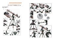
Stage 3: assembling the buoyancy <strong>hu</strong>ll, parts 3.1 - 3.4<br />
Red mark<br />
Pressure vessel 3.2<br />
The red mark indicates the rear face of the pressure vessel 32.<br />
• Cut the T-section rail 3.1 to a length of exactly 320 mm.<br />
• The rail has to be glued in the buoyancy <strong>hu</strong>ll, ending 13 mm short of the front rim of the <strong>hu</strong>ll. Mark<br />
this 13 mm dimension on the inside at the front.<br />
Place the rail 3.1 in the buoyancy <strong>hu</strong>ll 3.2, lining it up with the 13 mm mark.<br />
• Fix the buoyancy <strong>hu</strong>ll on the workbench so that it cannot roll.<br />
43