
Erfolgreiche ePaper selbst erstellen
Machen Sie aus Ihren PDF Publikationen ein blätterbares Flipbook mit unserer einzigartigen Google optimierten e-Paper Software.
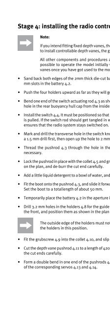
Stage 4: installing the radio control system, parts 4.1 - 4.19<br />
Note:<br />
If you intend fitting fixed depth vanes, the depth vane servo 4.13 is not needed. If you wish<br />
to install controllable depth vanes, the grubscrew 4.9 and the collet 4.10 are not required.<br />
All other components and procedures are the same for both versions. As a result, it is<br />
possible to operate the model initially with fixed depth vanes, then install controllable<br />
vanes once you have got used to the model.<br />
• Sand back both edges of the 2mm thick die-cut battery holders 4.1 until they fit easily into the 1.5<br />
mm slots in the battery 4.2.<br />
• Push the four holders upward as far as they will go, and fix them in place with instant glue.<br />
• Bend one end of the switch actuating rod 4.3 as shown on the plan view, and slip it through the inner<br />
hole in the rear buoyancy <strong>hu</strong>ll cap from the inside.<br />
• Install the switch 4.4. It must be positioned so that it is „On“ when pulled back, i.e. when the pushrod<br />
is pulled. If the switch rod should get tangled in weed when the boat is running, this arrangement<br />
ensures that the radio system stays switched on.<br />
• Mark and drill the transverse hole in the switch knob exactly as shown in the detail drawing „Y“. Use<br />
a 1.5 mm drill first, then open up the hole to 2 mm diameter.<br />
• Thread the pushrod 4.3 through the hole in the knob from the underside, bending the rod as<br />
necessary.<br />
• Lock the pushrod in place with the collet 4.5 and grubscrew 4.6. Cut the pushrod to the length shown<br />
on the plan, and de-burr the cut end carefully.<br />
• Add a little liquid detergent to a bowl of water, and moisten the inside of the flexible boot 4.7 with it.<br />
• Fit the boot onto the pushrod 4.3, and slide it forward as far as the stub on the buoyancy <strong>hu</strong>ll cap 1.8.<br />
Set the boot to a totallength of about 50 mm.<br />
• Temporarily place the battery 4.2 in the aperture in the insert plate.<br />
• Drill 3.2 mm holes in the holders 4.8 for the guide tubes 2.15 and 2.16, fit them onto the tubes from<br />
the front, and position them as shown in the plan view.<br />
The outside edge of the holders must not project beyond the edge of the insert plate. Glue<br />
the holders in this position.<br />
• Fit the grubscrew 4.9 into the collet 4.10, and slip the collet onto the depth vane guide tube 2.15.<br />
• Cut the depth vane pushrod 4.11 to a length of 420 mm, the rudder pushrod 4.12 to 495 mm. De-burr<br />
the cut ends carefully.<br />
• Form a double bend in one end of the pushrods 4.11 and 4.12, and connect them to the output disc<br />
of the corresponding servos 4.13 and 4.14.<br />
45