Sie wollen auch ein ePaper? Erhöhen Sie die Reichweite Ihrer Titel.
YUMPU macht aus Druck-PDFs automatisch weboptimierte ePaper, die Google liebt.
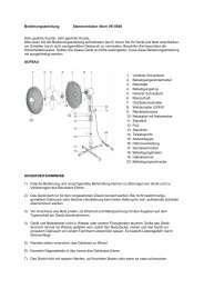
• Drill out the central (stepped) hole in the rear buoyancy <strong>hu</strong>ll cap 1.8 to 6.5 mm diameter right through.<br />
• Push the stern tube 1.9 and gearbox housing through the buoyancy <strong>hu</strong>ll cap.<br />
• File out the bottom end of the lubricating nipple holder 1.10 to a half-round shape, to match the<br />
curvature of the stern tube, and solder it to the tube, as shown on the plan.<br />
• Drill a 3 mm hole into the stern tube, drilling through the holder. Blow out the drilling swarf.<br />
• The lubricating nipple 1.11 can now be glued to the holder: apply Stabilit Express thinly all round the<br />
flange of the nipple, and push the parts together.<br />
• Slide the propeller shaft 1.12 into the stern tube. Apply grease to the gear to lubricate it.<br />
• Fit the housing cover 1.13 into the gearbox housing. Insert the motor and tighten the screws 1.14.<br />
Stage 2: insert for the motor / gearbox assembly and<br />
radio control system, parts 2.1 - 2.16<br />
• Screw the nut 2.1 onto the threaded rod 2.2.<br />
• Drill and file out the transverse slot for the nut 2.1 in the insert plate 2.3, starting at the marked<br />
points. When the slot is finished, file out the lengthwise slot for the threaded rod. Cover the slots on<br />
one side with adhesive tape.<br />
• Place the insert plate 2.3 on a flat table, with the slots for the nut and the threaded rod projecting<br />
over the edge.<br />
• Screw the nut in or out on the threaded rod until it matches the position of the transverse slot. Place<br />
the threaded rod in the insert. Apply Stabilit Express to the slots to glue the assembly 2.1 / 2.2 in<br />
place.<br />
• Cut the openings for the battery and the gearbox housing.<br />
• Cut a hole in the bulkhead 2.4 to take the motor lead 1.5.<br />
• Place the insert plate 2.3 on a flat surface.<br />
• Position the two bulkheads 2.4 and 2.5 on the plate 2.3 as shown on the plan, check that they are<br />
upright, and fix them in place with instant glue.<br />
• Push the full-length T-section rails 2.6 through the bulkheads and fix them in place with instant glue.<br />
Allow a drop of instant glue to run along the joints to fix the rails to the plate and the bulkheads.<br />
• Cut away excess rail length at front and rear, following the shape of the insert plate. Sand the rails to<br />
the correct angle to match the inside shape of the buoyancy <strong>hu</strong>ll caps.<br />
• Glue the front and rear gussets 2.7 and 2.8 in place, as shown on the plan. The gussets must rest<br />
against the rails.<br />
• Glue the two spacer plates 2.9 to the insert plate, flush with the inside edge of the rear slot for the<br />
stern tube.<br />
42