
You also want an ePaper? Increase the reach of your titles
YUMPU automatically turns print PDFs into web optimized ePapers that Google loves.
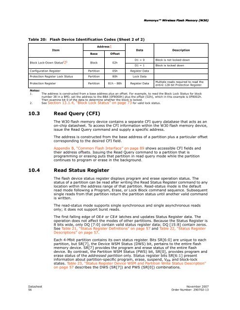
Table 20: <strong>Flash</strong> Device Identification Codes (Sheet 2 of 2)<br />
Item<br />
10.3 Read Query (CFI)<br />
Address1<br />
Base Offset<br />
Numonyx <strong>Wireless</strong> <strong>Flash</strong> <strong>Memory</strong> (<strong>W30</strong>) (<strong>W30</strong>)<br />
Block Lock-Down Status ( 2 )<br />
Block 02h<br />
D1 = 0 Block is not locked-down<br />
D1 = 1 Block is locked down<br />
Configuration Register Partition 05h Register Data<br />
Protection Register Lock Status Partition 80h Lock Data<br />
Protection Register<br />
Notes:<br />
Partition 81h - 88h Register Data<br />
Multiple reads required to read the<br />
entire 128-bit Protection Register.<br />
1. The address is constructed from a base address plus an offset. For example, to read the Block Lock Status for block<br />
number 38 in a BPD, set the address to the BBA (0F8000h) plus the offset (02h), which in this example is 0F8002h.<br />
Then examine bit 0 of the data to determine whether the block is locked.<br />
2. See Section 13.1.4, “Block Lock Status” on page 73 for valid lock status.<br />
The <strong>W30</strong> flash memory device contains a separate CFI query database that acts as an<br />
on-chip datasheet. To access the CFI information within the <strong>W30</strong> flash memory device,<br />
issue the Read Query command and supply a specific address.<br />
The address is constructed from the base address of a partition plus a particular offset<br />
corresponding to the desired CFI field.<br />
Appendix B, “Common <strong>Flash</strong> Interface” on page 89 shows accessible CFI fields and<br />
their address offsets. Issuing the Read Query command to a partition that is<br />
programming or erasing puts that partition in read query mode while the partition<br />
continues to program or erase in the background.<br />
10.4 Read Status Register<br />
Data Description<br />
The flash device status register displays program and erase operation status. The<br />
status of a partition can be read after writing the Read Status Register command to any<br />
location within the address range of that partition. Read-status mode is the default<br />
read mode following a Program, Erase, or Lock Block command sequence. Subsequent<br />
single reads from that partition return the partition status until another valid command<br />
is written.<br />
The read-status mode supports single synchronous and single asynchronous reads<br />
only; it does not support burst reads.<br />
The first falling edge of OE# or CE# latches and updates Status Register data. The<br />
operation does not affect the modes of other partitions. Because the Status Register is<br />
8 bits wide, only DQ [7:0] contain valid status register data; DQ [15:8] contain zeros.<br />
See Table 21, “Status Register Definitions” on page 57 and Table 22, “Status Register<br />
Descriptions” on page 57.<br />
Each 4-Mbit partition contains its own status register. Bits SR[6:0] are unique to each<br />
partition, but SR[7], the Device WSM Status (DWS) bit, pertains to the entire flash<br />
memory device. SR[7] provides the program and erase status of the entire flash<br />
device. By contrast, the Partition WSM Status (PWS) bit, SR[0], provides program and<br />
erase status of the addressed partition only. Status register bits SR[6:1] present<br />
information about partition-specific program, erase, suspend, V PP , and block-lock<br />
states. Table 23, “Status Register Device WSM and Partition Write Status Description”<br />
on page 57 describes the DWS (SR[7]) and PWS (SR[0]) combinations.<br />
Datasheet November 2007<br />
56 Order Number: 290702-13