
Create successful ePaper yourself
Turn your PDF publications into a flip-book with our unique Google optimized e-Paper software.
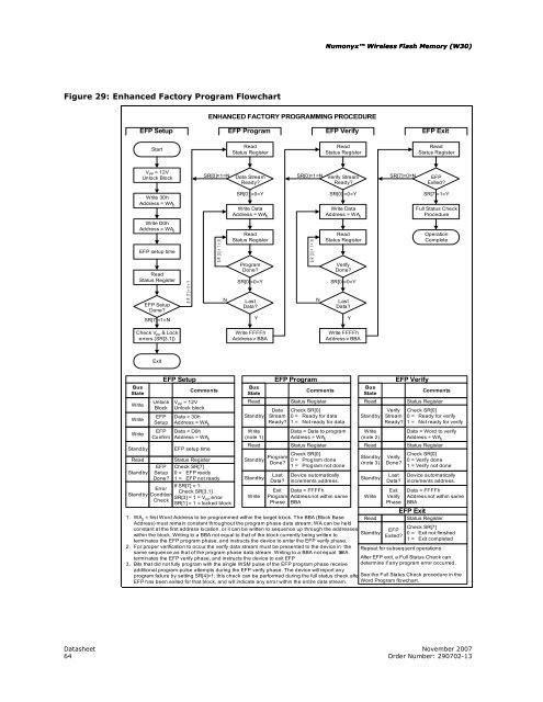
Figure 29: Enhanced Factory Program Flowchart<br />
Standby<br />
EFP Setup<br />
Start<br />
V PP = 12V<br />
Unlock Block<br />
Write 30h<br />
Address = WA 0<br />
Write D0h<br />
Address = WA 0<br />
EFP setup time<br />
Read<br />
Status Register<br />
EFP Setup<br />
Done?<br />
SR[7]=1=N<br />
Check V PP & Lock<br />
errors (SR[3,1])<br />
Exit<br />
EFP<br />
Setup<br />
Done?<br />
S R [7 ]= 0 = Y<br />
ENHANCED FACTORY PROGRAMMING PROCEDURE<br />
SR[0]=1=N<br />
S R [0 ]= 1 = N<br />
Status Register<br />
Check SR[7]<br />
0 = EFP ready<br />
1 = EFP not ready<br />
N<br />
Write Data<br />
Address = WA 0<br />
Read<br />
Status Register<br />
Program<br />
Done?<br />
SR[0]=0=Y<br />
Last<br />
Data?<br />
Y<br />
Write FFFFh<br />
Address ≠ BBA<br />
Standby<br />
Numonyx <strong>Wireless</strong> <strong>Flash</strong> <strong>Memory</strong> (<strong>W30</strong>) (<strong>W30</strong>)<br />
EFP Program EFP Verify EFP Exit<br />
Read<br />
Status Register<br />
Data Stream<br />
Ready?<br />
SR[0] =0=Y<br />
Datasheet November 2007<br />
64 Order Number: 290702-13<br />
Last<br />
Data?<br />
SR[0]=1=N<br />
S R [0 ]= 1 = N<br />
N<br />
Device automatically<br />
increments address.<br />
Read<br />
Status Register<br />
Verify Stream<br />
Ready?<br />
SR[0] =0=Y<br />
Write Data<br />
Address = WA 0<br />
Read<br />
Status Register<br />
Verify<br />
Done?<br />
SR[0]=0=Y<br />
Last<br />
Data?<br />
Y<br />
Write FFFFh<br />
Address ≠ BBA<br />
Standby<br />
SR[7]=0=N<br />
Last<br />
Data?<br />
Read<br />
Status Register<br />
EFP<br />
Exited?<br />
SR[7]=1=Y<br />
Full Status Check<br />
Procedure<br />
Operation<br />
Complete<br />
EFP Setup EFP Program EFP Verify<br />
Bus<br />
State<br />
Comments<br />
Bus<br />
State<br />
Comments<br />
Bus<br />
State<br />
Comments<br />
Write<br />
Unlock<br />
Block<br />
V = 12V<br />
PP<br />
Unlock block<br />
Read<br />
Data<br />
Status Register<br />
Check SR[0]<br />
Read<br />
Verify<br />
Status Register<br />
Check SR[0]<br />
Write<br />
EFP<br />
Setup<br />
Data = 30h<br />
Address = WA0 Standby Stream<br />
Ready?<br />
0 =<br />
1 =<br />
Ready for data<br />
Not ready for data<br />
Standby Stream<br />
Ready?<br />
0 =<br />
1 =<br />
Ready for verify<br />
Not ready for verify<br />
Write<br />
EFP<br />
Confirm<br />
Data = D0h<br />
Address = WA0 Write<br />
(note 1)<br />
Data = Data to program<br />
Address = WA0 Write<br />
(note 2)<br />
Data = Word to verify<br />
Address = WA0 Standby EFP setup time<br />
Read<br />
Status Register<br />
Read<br />
Status Register<br />
Read<br />
Check SR[0]<br />
Program<br />
Standby<br />
0 = Program done<br />
Done?<br />
1 = Program not done<br />
Standby<br />
(note 3)<br />
Verify<br />
Done?<br />
Check SR[0]<br />
0 = Verify done<br />
1 = Verify not done<br />
Device automatically<br />
increments address.<br />
If SR[7] = 1:<br />
Error<br />
Check SR[3,1]<br />
Standby Condition<br />
SR[3] = 1 = V error<br />
Check<br />
PP<br />
SR[1] = 1 = locked block<br />
Write<br />
Exit Data = FFFFh<br />
Program Addressnot within same<br />
Phase BBA<br />
Write<br />
Exit<br />
Verify<br />
Phase<br />
Data = FFFFh<br />
Addressnot within same<br />
BBA<br />
1. WA = first Word Address to be programmed within the target block. The BBA (Block Base<br />
0 Read<br />
EFP Exit<br />
Status Register<br />
Address) must remain constant throughout the program phase data stream; WA can be held<br />
constant at the first address location, or it can be written to sequence up through the addresses<br />
within the block. Writing to a BBA not equal to that of the block currently being written to<br />
Standby<br />
terminates the EFP program phase, and instructs the device to enter the EFP verify phase.<br />
EFP<br />
Exited?<br />
Check SR[7]<br />
0 = Exit not finished<br />
1 = Exit completed<br />
2. For proper verification to occur, the verify data stream must be presented to the device in the<br />
same sequence as that of the program phase data stream. Writing to a BBA not equal to WA<br />
terminates the EFP verify phase, and instructs the device to exit EFP.<br />
3. Bits that did not fully program with the single WSM pulse of the EFP program phase receive<br />
Repeat for subsequent operations.<br />
After EFP exit, a Full Status Check can<br />
determine if any program error occurred.<br />
additional program-pulse attempts during the EFP verify phase. The device will report any<br />
program failure by setting SR[4]=1; this check can be performed during the full status check afterSee<br />
the Full Status Check procedure in the<br />
EFP has been exited for that block, and will indicate any error within the entire data stream. Word Program flowchart.