Create successful ePaper yourself
Turn your PDF publications into a flip-book with our unique Google optimized e-Paper software.
Numonyx <strong>Wireless</strong> <strong>Flash</strong> <strong>Memory</strong> (<strong>W30</strong>)<br />
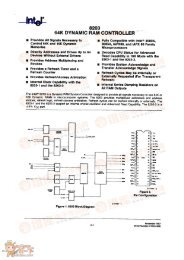
Figure 34: Locking Operations Flowchart<br />
Optional<br />
Start<br />
Write 60h<br />
Block Address<br />
Write 01,D0,2Fh<br />
Block Address<br />
Write 90h<br />
BBA + 02h<br />
Read Block Lock<br />
Status<br />
Locking<br />
Change?<br />
Yes<br />
Write FFh<br />
Partition Address<br />
Lock Change<br />
Complete<br />
13.2 Protection Register<br />
No<br />
LOCKING OPERATIONS PROCEDURE<br />
Bus<br />
Command Comments<br />
Operation<br />
Write<br />
Write<br />
Write<br />
(Optional)<br />
Read<br />
(Optional)<br />
Standby<br />
(Optional)<br />
Write<br />
The <strong>W30</strong> flash memory device includes a 128-bit Protection Register. This protection<br />
register is used to increase system security and for identification purposes. The<br />
protection register value can match the flash device to the system CPU or ASIC to<br />
prevent flash device substitution.<br />
• The lower 64 bits within the protection register are programmed by Numonyx with<br />
a unique number in each flash device.<br />
• The upper 64 OTP bits within the protection register are left for the customer to<br />
program. Once programmed, the customer segment can be locked to prevent<br />
further programming.<br />
Note: The individual bits of the user segment of the protection register are OTP, not the<br />
register in total. The user can program each OTP bit individually, one at a time, if<br />
desired. However, after the protection register is locked, the entire user segment is<br />
locked and no more user bits can be programmed.<br />
The protection register shares some of the same internal flash device resources as the<br />
parameter partition. Therefore, RWW is allowed only between the protection register<br />
and the main partitions. Table 26 describes the operations allowed in the protection<br />
register, parameter partition, and main partition during RWW and RWE.<br />
November 2007 Datasheet<br />
Order Number: 290702-13 75<br />
Lock<br />
Setup<br />
Lock,<br />
Unlock, or<br />
Lockdown<br />
Confirm<br />
Read ID<br />
Plane<br />
Block Lock<br />
Status<br />
Read<br />
Array<br />
Data = 60h<br />
Addr = Block to lock/unlock/lock-down (BA)<br />
Data = 01h (Lock block)<br />
D0h (Unlock block)<br />
2Fh (Lockdown block)<br />
Addr = Block to lock/unlock/lock-down (BA)<br />
Data = 90h<br />
Addr = BBA + 02h<br />
Block Lock status data<br />
Addr = BBA + 02h<br />
Confirm locking change on DQ[1:0].<br />
(See Block Locking State Transitions Table<br />
for valid combinations.)<br />
Data = FFh<br />
Addr = Any address in same partition