- Page 1 and 2:
INTRODUCTION Chapters 1. Operation
- Page 3 and 4:
TABLE OF CONTENTS INTRODUCTION ....
- Page 5 and 6:
2.2.11 Masimo SET Technology. ....
- Page 7 and 8:
7.5.13 Verification of Accutorr Plu
- Page 9 and 10:
1.0 OPERATION CONTENTS OF THIS CHAP
- Page 11 and 12:
1.2 CONTROLS AND INDICATORS This se
- Page 13:
1 2 3 4 5 6 7 8 SYS. DIA. NIBP Sp0
- Page 17 and 18:
11. Select Key (Accutorr Plus model
- Page 19 and 20:
29. Set Alarms Key This key is used
- Page 21 and 22:
1.2.2 Rear Panel Figure 1-5 Rear Pa
- Page 23 and 24:
1.2.4 Recorder Module Figure 1-7 Re
- Page 25 and 26:
1.3. OPERATION This section of the
- Page 27 and 28:
1.3.2.3 Room Number and Bed Letter
- Page 29 and 30:
2. Attach the cuff hose to the NIBP
- Page 31 and 32:
1.3.4 AUTOMATIC NIBP MEASUREMENTS (
- Page 33 and 34:
1.3.5 ALARMS The Accutorr Plus prov
- Page 35 and 36:
1.3.5.3 How to Mute Alarms When an
- Page 37 and 38:
1.3.6.2 To View the Stored Measurem
- Page 39 and 40:
1.3.8 SETTING THE LCD CONTRAST (Vie
- Page 41 and 42:
1.3.10 SpO2 MEASUREMENTS (Accutorr
- Page 43 and 44:
C. Sensor Connection to the Accutor
- Page 45 and 46:
1.3.10.2 Sequence for establishing
- Page 47 and 48:
If patient movement presents a prob
- Page 49 and 50:
interference; and placement of a se
- Page 54 and 55:
1.3.12 RECORDER (optional) The Accu
- Page 56 and 57:
1.3.14 BATTERY OPERATION When the A
- Page 58 and 59:
User Configuration Number Function
- Page 60 and 61:
1.3.17 HOW TO ATTACH OPTIONAL THERM
- Page 62 and 63:
1.3.19 PLACEMENT OF RECORDER PAPER
- Page 64 and 65:
2.2 DETAILED CIRCUIT DESCRIPTIONS T
- Page 66 and 67:
Notes: 1. Detailed functional descr
- Page 68 and 69:
Notes: 1. Detailed functional descr
- Page 70 and 71:
Notes: 1. Detailed functional descr
- Page 72 and 73:
3. Perform NIBP functions. start m
- Page 74 and 75:
FUNCTIONAL GROUP SIGNALS SIGNAL DES
- Page 76 and 77:
Real Time Clock and NV RAM (RTC), U
- Page 78 and 79:
Keypad interface The keypad is made
- Page 80 and 81:
Software Control There are no softw
- Page 82 and 83:
Figure 2-5 Recorder Module Control
- Page 84 and 85:
2.2.5 SpO2 Module: (Accutorr Plus M
- Page 86 and 87:
Figure 2-7 SpO2 Block Diagram Digit
- Page 88 and 89:
2.2.7 Communication Board The Accut
- Page 90 and 91:
Figure 2-9 LCD Inverter Module Bloc
- Page 92 and 93:
Figur2-11 Datascope Interface Circu
- Page 94 and 95:
Figure 2-12 2.2.12 Masimo Interface
- Page 96 and 97:
Figure 2-13 Tone-Processor Module F
- Page 98 and 99:
NIBP Measurement Cycle Time Less th
- Page 100 and 101:
Masimo ® SpO2 Range: 40-100% SpO2
- Page 102 and 103:
3.2 Safety Characteristics Risk (Le
- Page 105 and 106:
4.0 REPAIR INFORMATION CONTENTS OF
- Page 107 and 108:
2. Use the proper equipment. Specia
- Page 109 and 110:
4.5.1 Isolating the Problem, System
- Page 111 and 112:
has been received by the Accutorr P
- Page 113 and 114:
4.6 DISASSEMBLY INSTRUCTIONS PRECAU
- Page 115 and 116:
4.6.7 Removal of the Motor Filter (
- Page 117 and 118:
4.6.14 Thermometer, Predictive (opt
- Page 119:
5.0 ASSEMBLY AND SCHEMATIC DIAGRAMS
- Page 151: Schematic Drawing Main Power Supply
- Page 163 and 164: 6.0 REPLACEMENT PARTS CONTENTS OF T
- Page 165 and 166: 6.7 ABBREVIATIONS The following abb
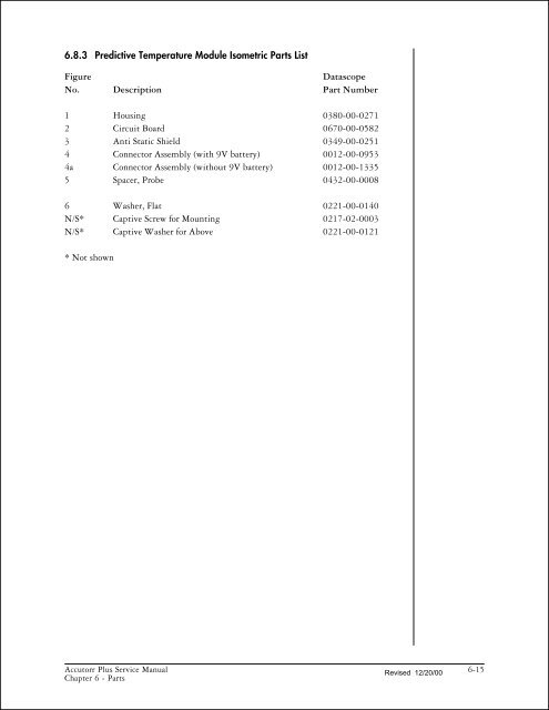
- Page 167 and 168: 6.8 ISOMETRIC DRAWINGS AND PARTS LI
- Page 169 and 170: Figure Datascope No. Description Pa
- Page 171 and 172: With NELLCOR SpO2 only Monitor Conf
- Page 173: This page intentionally left blank.
- Page 178 and 179: 1 2 3 6-16 Accutorr Plus Service Ma
- Page 180 and 181: 6-18 Re vised 12/20/00 Accutorr Plu
- Page 182: This page intentionally left blank.
- Page 185 and 186: Recorder Board Assembly 0670-00-058
- Page 187 and 188: NIBP Circuit Board Assembly 0670-00
- Page 189 and 190: NIBP Circuit Board Assembly 0670-00
- Page 191 and 192: SpO2 Board Assembly 0670-00-0593-03
- Page 193: CPU/LED Board 0670-00-0650-03/04 It
- Page 196 and 197: CPU/LED Board 0670-00-0650-03/04 It
- Page 198 and 199: Power Supply, Sealed Lead Acid 0014
- Page 200 and 201: Power Supply, Sealed Lead Acid 0014
- Page 202 and 203: Power Sup ply, Lith ium Ion 0014-00
- Page 204 and 205: Nellcor Interface BD P/N 0670-00-06
- Page 206 and 207: Masimo SpO2 Assy 0670-00-0716 Item
- Page 208 and 209: This page intentionally left blank.
- Page 210 and 211: Status and Error Code Table The Acc
- Page 212 and 213: 7.4 POWER-UP SEQUENCE, INTERNAL TES
- Page 214 and 215: 7.5.3 Keypad Test 1. Press the Room
- Page 216 and 217: 7.5.6.1 Recorder Print Head Adjustm
- Page 218 and 219: for the respective over pressure li
- Page 220 and 221: Pressing the Deflate key at any tim
- Page 222 and 223: 7.6 PREDICTIVE THERMOMETER VERIFICA
- Page 224 and 225: 7.6.4 Temperature Verification Test
- Page 226 and 227:
7.7 BATTERY TEST FOR ACCUTORR PLUS
- Page 228 and 229:
7.8 NIBP NORMAL OPERATION 1. Press
- Page 230 and 231:
SYS. DIA. NIBP Sp02 SpO 2 20/05 20/
- Page 232 and 233:
This page intentionally left blank.
- Page 234 and 235:
8.3 PREVENTIVE MAINTENANCE SCHEDULE
- Page 236:
Printed in U.S.A. 0070-10-0429 Rev