Accutorr Plus Service Manual - Mindray
Accutorr Plus Service Manual - Mindray
Accutorr Plus Service Manual - Mindray
You also want an ePaper? Increase the reach of your titles
YUMPU automatically turns print PDFs into web optimized ePapers that Google loves.
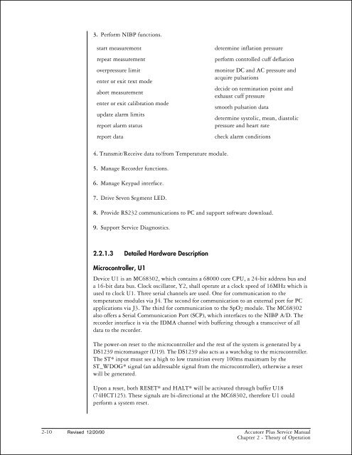
3. Perform NIBP functions.<br />
start measurement<br />
repeat measurement<br />
overpressure limit<br />
enter or exit text mode<br />
abort measurement<br />
enter or exit calibration mode<br />
update alarm limits<br />
report alarm status<br />
report data<br />
4. Transmit/Receive data to/from Temperature module.<br />
5. Manage Recorder functions.<br />
6. Manage Keypad interface.<br />
7. Drive Seven Segment LED.<br />
8. Provide RS232 communications to PC and support software download.<br />
9. Support <strong>Service</strong> Diagnostics.<br />
2.2.1.3 Detailed Hardware Description<br />
determine inflation pressure<br />
perform controlled cuff deflation<br />
monitor DC and AC pressure and<br />
acquire pulsations<br />
decide on termination point and<br />
exhaust cuff pressure<br />
smooth pulsation data<br />
determine systolic, mean, diastolic<br />
pressure and heart rate<br />
check alarm conditions<br />
Microcontroller, U1<br />
Device U1 is an MC68302, which contains a 68000 core CPU, a 24-bit address bus and<br />
a 16-bit data bus. Clock oscillator, Y2, shall operate at a clock speed of 16MHz which is<br />
used to clock U1. Three serial channels are used. One for communication to the<br />
temperature modules via J4. The second for communication to an external port for PC<br />
applications via J3. The third for communication to the SpO2 module. The MC68302<br />
also offers a Serial Communication Port (SCP), which interfaces to the NIBP A/D. The<br />
recorder interface is via the IDMA channel with buffering through a transceiver of all<br />
data to the recorder.<br />
The power-on reset to the microcontroller and the rest of the system is generated by a<br />
DS1239 micromanager (U19). The DS1239 also acts as a watchdog to the microcontroller.<br />
The ST* input must see a high to low transition every 100ms maximum by the<br />
ST_WDOG* signal (an addressable signal from the microcontroller), otherwise a reset<br />
will be generated.<br />
Upon a reset, both RESET* and HALT* will be activated through buffer U18<br />
(74HCT125). These signals are bi-directional at the MC68302, therefore U1 could<br />
perform a system reset.<br />
2-10 Revised 12/20/00<br />
<strong>Accutorr</strong> <strong>Plus</strong> <strong>Service</strong> <strong>Manual</strong><br />
Chapter 2 - Theory of Operation


