

Accutorr Plus Service Manual - Mindray
Accutorr Plus Service Manual - Mindray
Accutorr Plus Service Manual - Mindray

You also want an ePaper? Increase the reach of your titles
YUMPU automatically turns print PDFs into web optimized ePapers that Google loves.
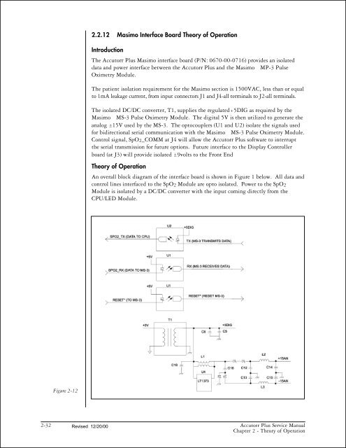
Figure 2-12<br />
2.2.12 Masimo Interface Board Theory of Operation<br />
Introduction<br />
The <strong>Accutorr</strong> <strong>Plus</strong> Masimo interface board (P/N: 0670-00-0716) provides an isolated<br />
data and power interface between the <strong>Accutorr</strong> <strong>Plus</strong> and the Masimo MP-3 Pulse<br />
Oximetry Module.<br />
The patient isolation requirement for the Masimo section is 1500VAC, less than or equal<br />
to 1mA leakage current, from input connectors J1 and J4-all terminals to J2-all terminals.<br />
The isolated DC/DC converter, T1, supplies the regulated+5DIG as required by the<br />
Masimo MS-3 Pulse Oximetry Module. The digital 5V is then utilized to generate the<br />
analog 15V used by the MS-3. The optocouplers (U1 and U2) isolate the signals used<br />
for bidirectional serial communication with the Masimo MS-3 Pulse Oximetry Module.<br />
Control signal, SpO2_COMM at J4 will allow the <strong>Accutorr</strong> <strong>Plus</strong> software to interrupt<br />
the serial transmission for future options. Future interface to the Display Controller<br />
board (at J3) will provide isolated 9volts to the Front End<br />
Theory of Operation<br />
An overall block diagram of the interface board is shown in Figure 1 below. All data and<br />
control lines interfaced to the SpO2 Module are opto isolated. Power to the SpO2<br />
Module is isolated by a DC/DC converter with the input coming directly from the<br />
CPU/LED Module.<br />
2-32 Revised 12/20/00<br />
<strong>Accutorr</strong> <strong>Plus</strong> <strong>Service</strong> <strong>Manual</strong><br />
Chapter 2 - Theory of Operation


