

Accutorr Plus Service Manual - Mindray
Accutorr Plus Service Manual - Mindray
Accutorr Plus Service Manual - Mindray

Create successful ePaper yourself
Turn your PDF publications into a flip-book with our unique Google optimized e-Paper software.
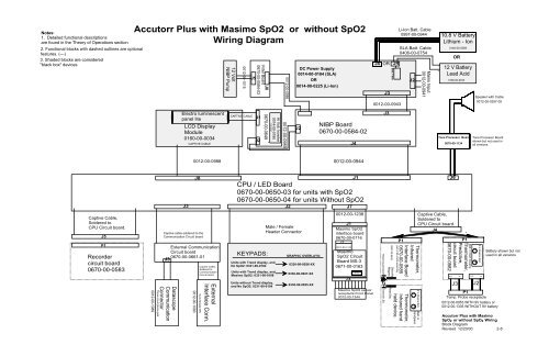
Notes:<br />
1. Detailed functional descriptions<br />
are found in the Theory of Operations section<br />
2. Functional blocks with dashed outlines are optional<br />
features. (---)<br />
3. Shaded blocks are considered<br />
"black box" devices<br />
Captive Cable,<br />
Soldered to<br />
CPU Circuit board.<br />
J5<br />
P1<br />
Recorder<br />
circuit board<br />
0670-00-0583<br />
<strong>Accutorr</strong> <strong>Plus</strong> with Masimo SpO2 or without SpO2<br />
Wiring Diagram<br />
0012-00-1089<br />
Three circuit phone jack<br />
LCD Display<br />
Module<br />
0160-00-0034<br />
J3<br />
J8<br />
External Communication<br />
Circuit board<br />
0670-00-0661-01<br />
J3<br />
Datascope<br />
Communication<br />
Connector<br />
Electro luminescent<br />
panel lite<br />
CAPTIVE CABLE<br />
Captive cable soldered to the<br />
Communication Circuit board<br />
0012-00-0988<br />
0012-00-1090<br />
Captive Cable,<br />
Soldered to<br />
Communication<br />
Circuit board.<br />
9 pin female DIN<br />
External<br />
Interface Conn.<br />
12 Volt<br />
NIBP Pump<br />
0012-00-1015<br />
CAPTIVE CABLE<br />
J5<br />
J6<br />
Filter Board<br />
0670-00-0584-03<br />
J1<br />
J2<br />
0670-00-0649<br />
100 VAC<br />
Hi Volt. Inverter<br />
0014-00-0180<br />
0012-00-0986<br />
J2<br />
NIBP Board<br />
0670-00-0584-02<br />
CPU / LED Board<br />
0670-00-0650-03 for units with SpO2<br />
0670-00-0650-04 for units Without SpO2<br />
KEYPADS:<br />
Units with Trend display, and<br />
No SpO2: 0331-00-0102<br />
Units with Trend display, and<br />
Masimo SpO2: 0331-00-0108<br />
Units without Trend display,<br />
and No SpO2: 0331-00-0104<br />
0012-00-0989<br />
J2<br />
Male / Female<br />
Header Connector<br />
DC Power Supply<br />
0014-00-0184 (SLA)<br />
OR<br />
0014-00-0225 (Li-Ion)<br />
GRAPHIC OVERLAYS:<br />
0330-00-0026-XX<br />
0330-00-0027-XX<br />
0330-00-0025-XX<br />
J7<br />
J1<br />
Masimo SpO2<br />
interface board<br />
0670-00-0716<br />
Masimo<br />
SpO2 Circuit<br />
Board MS-3<br />
0671-00-0163<br />
J 6<br />
J4<br />
0012-00-0944<br />
J1<br />
0012-00-1238<br />
J 2<br />
0012-00-1338<br />
J 5<br />
Masimo SpO2 sensor<br />
receptacle Front Panel<br />
0012-00-1344<br />
J4 OR<br />
J3<br />
J3<br />
Receiving photocell<br />
Transmit LED<br />
Batt. Fuse<br />
0997-00-0426<br />
Security<br />
Magnet<br />
Reed Sw.<br />
J4<br />
0012-00-0943<br />
held device.<br />
Li-Ion Batt. Cable<br />
0997-00-0944<br />
SLA Batt. Cable<br />
0406-00-0754<br />
P1<br />
J2<br />
Thermometer,<br />
Infrared<br />
Interface Board<br />
0670-00-0585<br />
part of IR cradle assembly<br />
Thermometer,<br />
Infrared hand<br />
_<br />
-<br />
+<br />
Captive Cable,<br />
Soldered to<br />
CPU Circuit board.<br />
J4<br />
9 V Alkaline Batt.<br />
+<br />
Batt. in<br />
handpiece<br />
Mains Input<br />
0012-00-0941<br />
10.8 V Battery<br />
Lithium - Ion<br />
0146-00-0069<br />
12 V Battery<br />
Lead Acid<br />
0146-00-0043<br />
J6<br />
P1<br />
Thermometer,<br />
Predictive,<br />
circuit board<br />
0670-00-0582<br />
2<br />
OR<br />
Tone Processor Board<br />
0670-00-1134<br />
J3<br />
1<br />
Batt. in main housing<br />
2<br />
_<br />
J2<br />
9 V Alkaline Batt.<br />
+<br />
1<br />
P1<br />
Temp. Probe receptacle<br />
Speaker with Cable<br />
0012-00-0257-05<br />
Tone Processor Board<br />
shown but not used in<br />
all versions.<br />
0012-00-0953 WITH 9V battery or<br />
0012-00-1335 WITHOUT 9V battery<br />
Battery shown but not<br />
used in all versions<br />
<strong>Accutorr</strong> <strong>Plus</strong> with Masimo<br />
SpO 2 or without SpO 2 Wiring<br />
Block Diagram<br />
Revised 12/20/00 2-8


